4000 Digital Series II Issue 2.1 Technical Manual
STA0381 Page 81
4.4.6 Controls and Indicators
Five LEDs are mounted on the leading edge of the board.; they give indication of the processor status;
their operation is detailed in the Installation Guide.
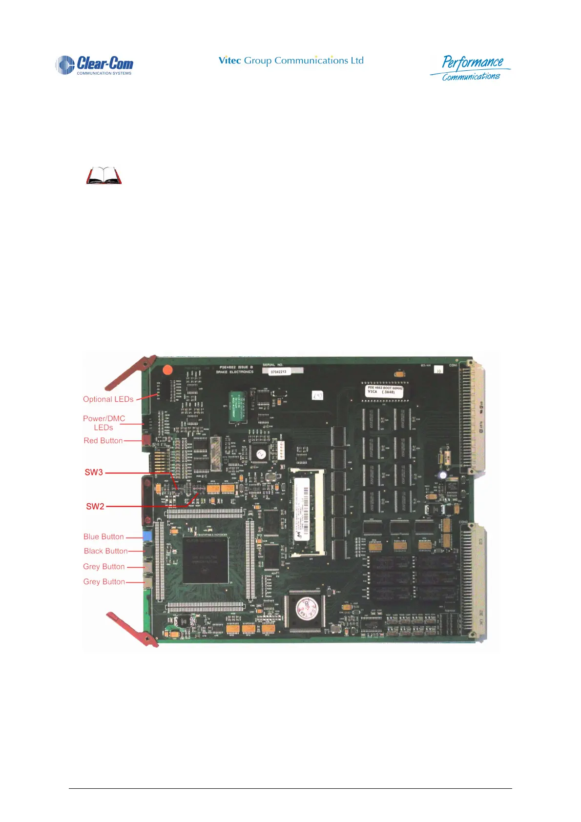
4.5 PDE4662 Central Processor Card
The PDE 4662 is the main processor card for 4000 Series II systems. It runs on a 68360 processor at
25 MHz and contains a 64kbyte/128kbyte boot PROM, one 8Mbyte SIMM DRAM, 256kbyte of battery
backed SRAM and 2 Mbytes of flash ROM. The 68360 contains four serial ports, two are used for
RS232/RS422 channels, one is for Ethernet, which will auto-sense AUI or 10BaseT interface, and the
other is used for inter-processor communication in the case of redundancy.
The card also drives the main audio clocks for a system: a 16MHz balanced ECL signal, a sample rate
clock and a x64 sample rate clock are also provided. It can also be synchronized to an externall source.
Figure 76 - PDE4662 - Central Processor Card
4.5.1 Card Location
The master processor card is located in slot 2 of the 4920 matrix or slot 1 of the 4420 matrix.
The slave (if fitted) is to be located in slot 1 of the 4920 or slot 2 of the 4420 matrix.
System Reset and 'Bootstrapping' the system are also explained in
the 4000 Digital Series Installation Guide.
 Loading...