4000 Digital Series II Issue 2.1 Technical Manual
STA0381 Page 75
4.3.2 Controls and Indicators
Three LEDs are mounted on the leading edge of the board; they indicate satisfactory +5V, -5V and
initialised status
4.3.3 Description
Sampling rate of 42.7kHz give a bandwidth of 20kHz. A control bus provides communication with a
central processor. The audio data input and output drive onto a multiplexed digital audio bus.
The card incorporates digital voice detectors (VOXs) on each input. These functions are both accessed
via the control bus and can be adjusted in CMAPSi. The audio outputs are provided as differential
voltage outputs. Balanced analogue audio inputs and outputs are available via optional transformers on
the PDE4622 CODEC RCU.
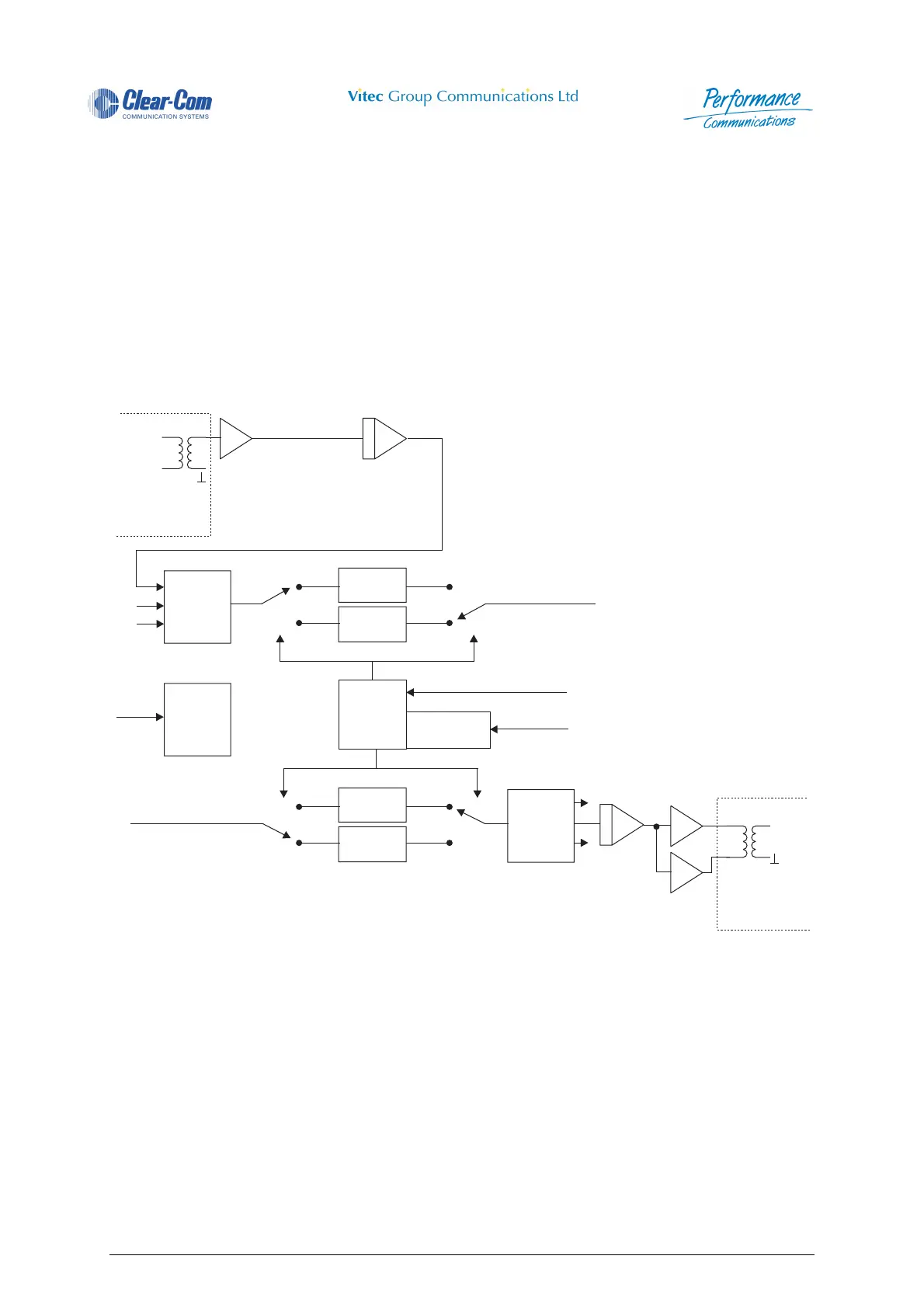
A block diagram of the CODEC card is shown below.
Figure 70 - PDE4631 Card Block Diagram
Audio Input
1of16
(Transformer
Optional)
Audio Output
1of16
(Transformer
Optional)
PDE4622 RCU
PDE4622 RCU
16-bit A/D
16-bit
D/A
16 to 1
MUX
PING
RAM
PING
RAM
PONG
RAM
PONG
RAM
16-Bit Source Bus
Clocks
VME Control
VME
Control
VOX
Detect
Mixing
Timeslot
Register
1to16
DEMUX
8-Bit Destination Bus
-1
 Loading...