Technical Manual Issue 2.1 4000 Digital Series II
Page 66 STA0381
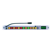
3.12 PDE 4552 Key Card
Figure 60 - PDE4552 Key Card
This card contains the 35 keys , and associated LEDs for the PD4226 panel.
The keys and LEDs are arranged in a matrix of rows and columns to reduce interconnection.
U1-5 perform the decode circuitry necessary to drive these signals.
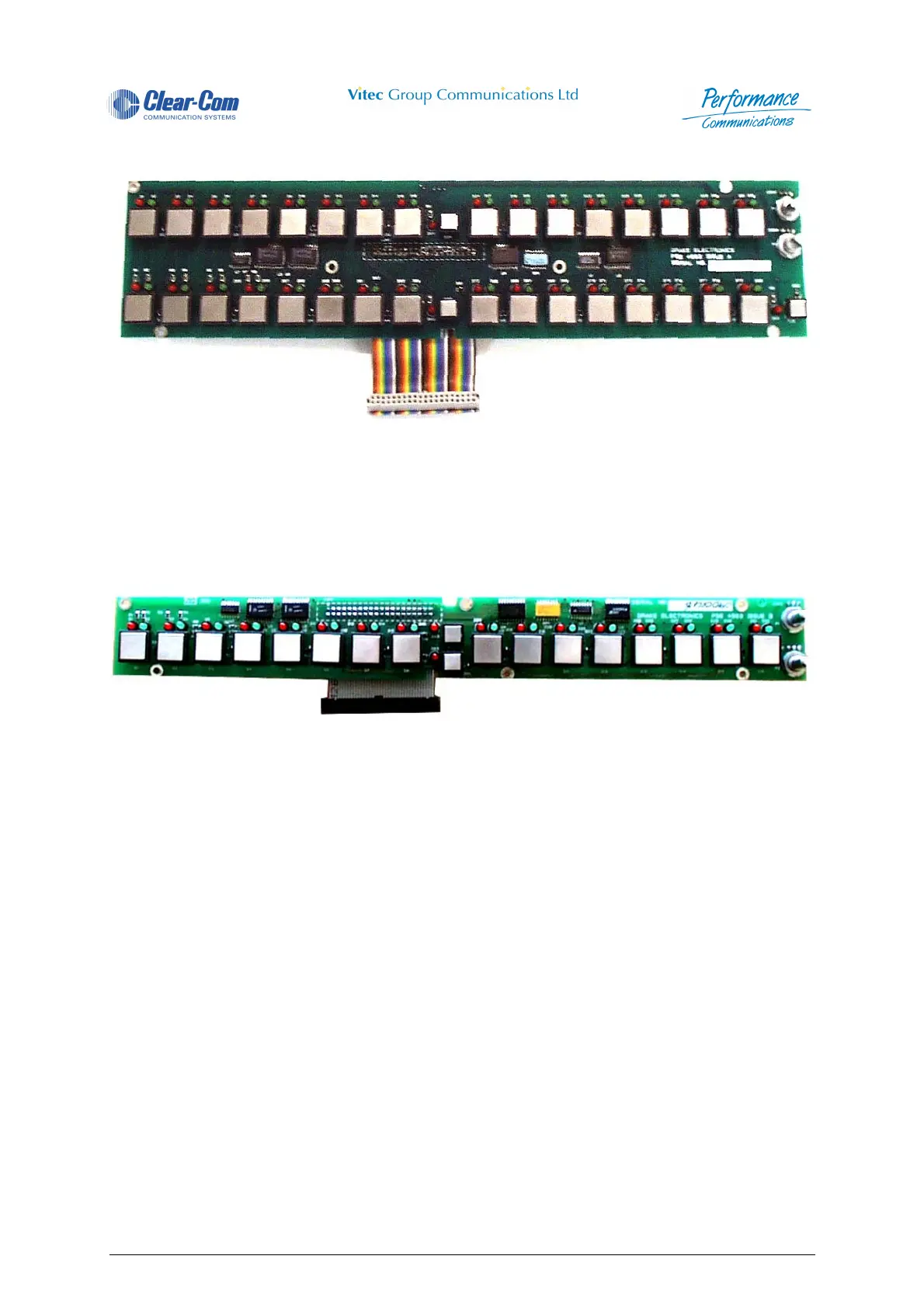
3.13 PDE 4553 Key Card
Figure 61 - PDE4553 Key Card
This card contains the 18 keys and associated LEDs for the PD4215 panel.
The keys and LEDs are arranged in a matrix of rows and columns to reduce interconnection.
U1-5 perform the decode circuitry necessary to drive these signals.
3.14 PDE 4554 Pot. Extension Card
This card contains the 20 level controls and driving circutiry for the PD4203 panel.
U18,4 & 6 are buffers for interfacing the circuitry to the main panel.
SW1 is a hex switch used for selecting the function of the PD4203 panel ie for key level control or i/o
level control.
(See the installation manual for details)
Each of the 20 level controls is multiplexed onto an A/D converter (U3) for the main processor card to
read the position.
 Loading...