Technical Manual Issue 2.1 4000 Digital Series II
Page 54 STA0381
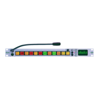
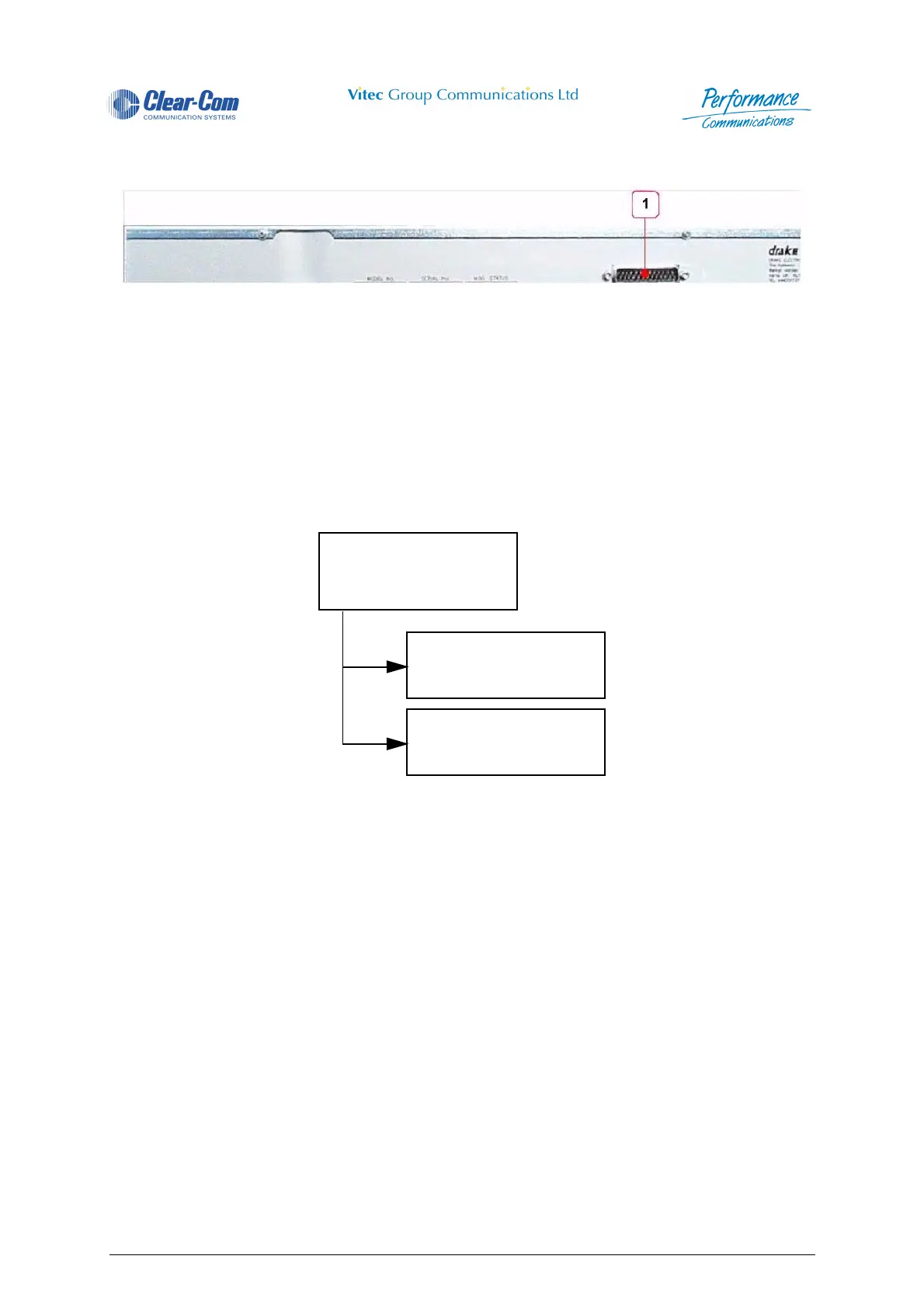
2.3.2.3 PD4206R/PD4206 Rear View
Figure 43 - PD4206R/PD4206 Rear view
2.3.2.4 PD4206R/PD4206 Extension Panel Description
The PD4206R/PD4206 1RU Extension Panels provide 4000 Control Panels with up to 20 additional
centrally assigned (via CMAPSi) DAKs.
2.3.2.5 PD4206R/PD4206 Components
2.3.2.6 PD4206R/PD4206 Mechanical Construction
The mechanical structure of the 4006 control panel is similar to that of the 4003.
2.3.2.7 PD4206R/PD4206 Wiring
The two main cards are connected together via ribbon cable. Ribbon cable is also used to connect the
PDE 3523 PCB to the 25-way D-type connector mounted on the rear of the unit. The Extension panel is
plugged via a 25-way D-type connector to the EXTENSION panel connector at the rear of the associated
Control Panel.
The maximum cable length between the 4006, main control panels is 1.5 metres.
1 Extension Connector
4206R/4206 20 KEY
EXTENSION PANEL
PDE 4558 EXTENSION
PANEL CARD
PDE 4505
SWITCH CARD
 Loading...