4000 Digital Series II Issue 2.1 Technical Manual
STA0381 Page 67
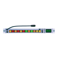
3.15 PDE 4556 Key/LED Display Card
Figure 62 - PDE4556 Key/LED Display card
This card contains the 20 keys and associated LEDs and LED displays for the PD4217 panel.
The keys and LEDs are arranged in a matrix of rows and columns to reduce interconnection.
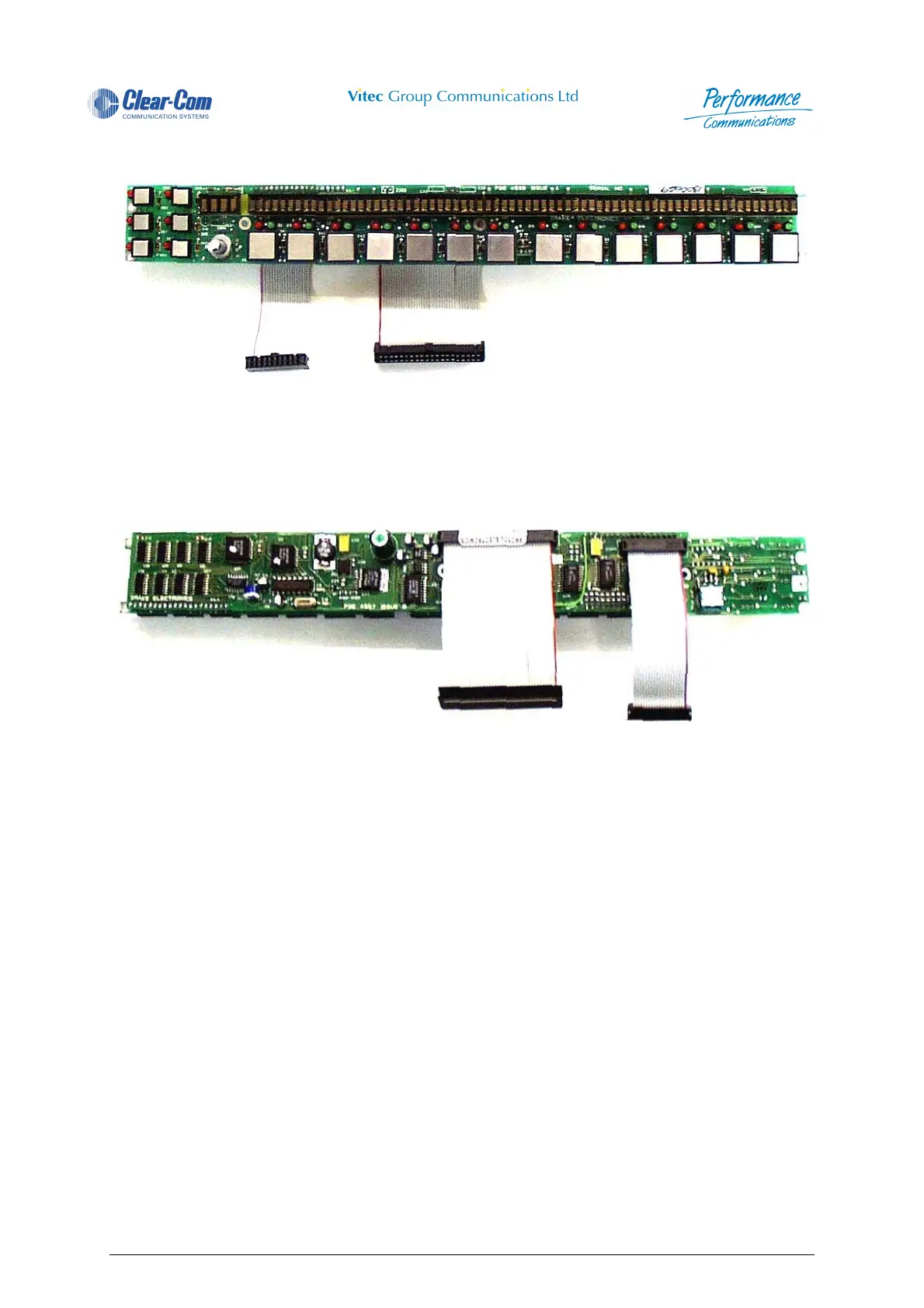
3.16 PDE 4557 Drive Card
Figure 63 - PDE4557 Drive Card
This card contains the necessary circuitry to interface the PDE4556 card to the PDE4535 panel
processor card.
A buck mode switching regulator ,U34,is used to generate 5Volts for the electronics , switches.&
displays.
U20,21,22,29 & 30 form the switch encoding logic which generates the necessary row and column scan
lines.
U4 provides DTMF tones decoded from U2 when the main panel processor card writes to LED positions.
RV1 is a preset for adjusting the amount of DTMF to the loudspeaker also controlled by the AUX
encoder on the front panel.
DTMF tones sent to the matrix are fixed in level.
U31 is a dual channel multiplying D to A converter which allows the main panel processor card to vary
the MAIN and AUX levels fed to the loudspeaker circuit.
The encoder for achieving this is read in on CON2.
U17 & 18 provide the decode addresses for writing data to the LED displays.
Each display receives its data from a parallel to serial converter U5,6,7,11,12,15 & 19.
 Loading...