4000 Digital Series II Issue 2.1 Technical Manual
STA0381 Page 95
Each LED is able to indicate the status of the channel that it represents. The various conditions are
shown below.
LED (on) - indicates a successful packet exchange, e.g., communication has been successful on that
channel.
LED (off) - indicates that the channel is unused.
LED flashing - indicates an error on that channel.
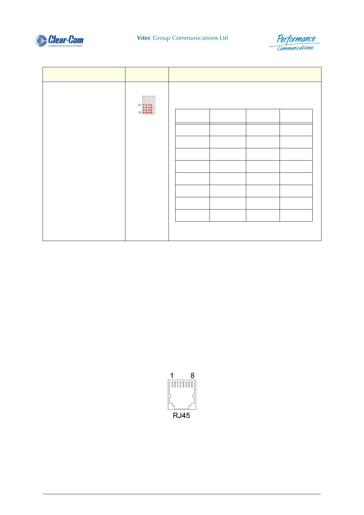
The PDE 4628 provides 16-channel communication with the 4000 Series II matrix via an RS422
interface. The pin-out configuration for the sixteen RJ45 connectors (CON 1-16) is indicated in the
following section.
4.8.5.4 Data and Audio Connections
Figure 83 - RS422 Connector (RJ45)
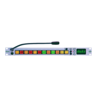
Channel Status Indicates the channel status - as shown below
Table 12: PDE 4628 Self Tests
Action LED Display Indication
Channel LED Channel LED
116926
2171027
3181128
4191229
5211331
6221432
7231533
8241634
 Loading...