4000 Digital Series II Issue 2.1 Technical Manual
STA0381 Page 85
• 6 - 14.2 KHz
• 7 - 12.8 KHz
• Link LK10. This link is factory set and should not be changed.
• Link LK11. This link sets the internal/external powering of the GPI opto-isolators as defined
below:
• Pins 1-2 linked - opto-isolators powered internally from Vcc (not isolated) (default).
• Pins 2-3 linked - opto-isolators powered externally (fully isolated)
• No links - opto-isolators disconnected
4.7.3 Connector details
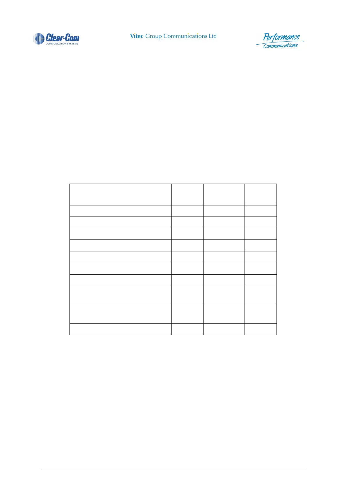
Table 4: PDE4663 - GPI Inputs
Description
Pin
Number
Description
Pin
Number
GPI Input 1 1 GPI Input 2 20
GPI Input 3 2 GPI Input 4 21
GPI Input 5 3 GPI Input 6 22
GPI Input 7 4 GPI Input 8 23
GPI Input 9 5 GPI Input 10 24
GPI Input 11 6 GPI Input 12 25
N.C. 7-16 N.C. 26-35
Isolated Inputs (requires external +7
Volts to +24 Volts applied)
17 Tech 0 Volts 36
Isolated Inputs (requires external +7
Volts to +24 Volts applied)
18 Tech 0 Volts 37
Common 24V Return 19
 Loading...