Technical Manual Issue 2.1 4000 Digital Series II
Page 68 STA0381
3.17 PDE 4558 Panel Electronics Card
This card contains the driving circutiry inside a PD4206 panel between the PDE4505 extension key card
and the main panel.
U6 & 7 are buffers for interfacing the circuitry to the main panel.
U3,4,5 & 26 form the switch encoding logic which generates the necessary row and column scan lines.
SW1 is a hex switch used for selecting the function of the PD4206 panel ie for panel position.
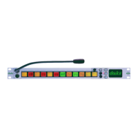
3.18 PDE 4566 Key/LCD Display Card
This card contains the 24 keys and associated LEDs and LCD display for the PD4294 key display panel.
The keys and LEDs are arranged in a matrix of rows and columns to reduce interconnection.
U18-21 perform the decode circuitry necessary to drive these signals.
A buck mode switching regulator ,U1,is used to generate 5Volts for the electronics and switches and
display.
The LCD display is driven by industry standard 80 column LCD drivers and LCD controller ic.
VR1 is a preset allowing for viewing angle adjustment of the displays.
3.19 PDE4609 8-channel telephone interface control card
PDE4609 is a 4000 series rear connection unit used for interfacing up to eight Telos units and takes the
place of four GPI cards.
Refer to the Series II Installation Guide for details of LEDs and switches.
3.19.1 PDE4609 Circuit description
Sheets 2 - 9 of the circuit diagram show the circuitry for each of the eight Telos interfaces.
The ‘sieze’ output is active low and triggers a momentary low pulse on the ‘drop’ output when released.
Dial-in codes are latched and decoded by two PLDs to provide a GPI bit number.
Sheet 10 of the circuit diagram shows the VME bus buffering and decoding necessary to make the card
appear as four GPI cards.
 Loading...