Technical Manual Issue 2.1 4000 Digital Series II
Page 12 STA0381
Figure 9 - PD4212R Front View
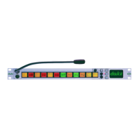
2.2.4.3 PD4212 Front View
Figure 10 - PD4212 Front View
NOTE: Microphone is shown here for illustrative purposes only. Contact Vitec Group Communications
for details of suitable products.
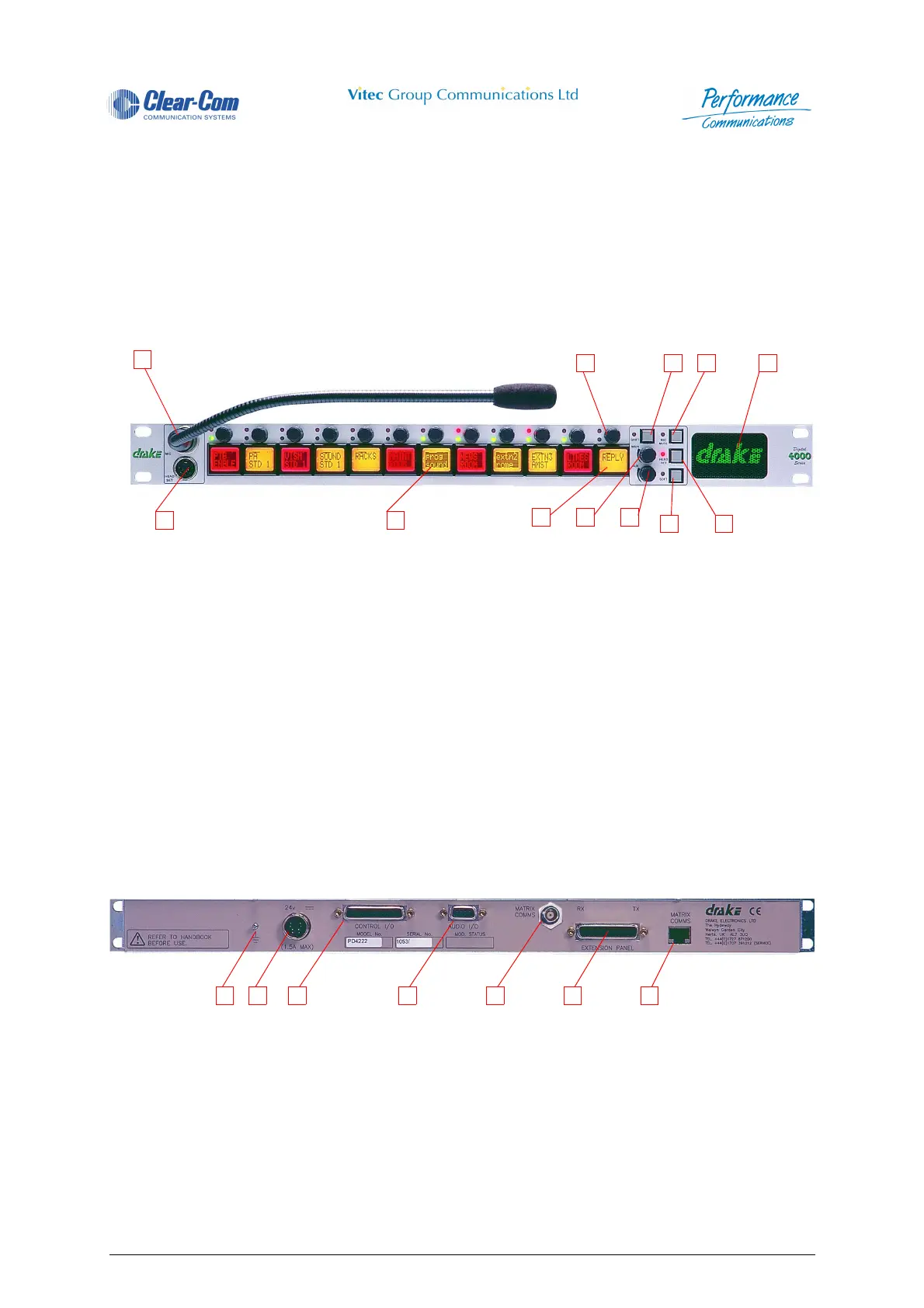
2.2.4.4 PD4212R/PD4212 Rear View
Figure 11 - PD4212 Rear View
4 Crosspoint Level Control 10 Soft Pushbutton
5 Loudspeaker 11 Headset Select Pushbutton
6 Auxiliary Volume Control 12 Headset Socket
1 Microphone Socket 7 Soft Pushbutton
2 Level Control 8 Auxiliary Volume Control
3 Shift Pushbutton 9 Main Volume Control
4 Microphone Mute Pushbutton 10 Reply Key
5 Loudspeaker 11 Direct Access Key (DAK)
6 Headset Select Pushbutton 12 Headset Socket
1 Earth Connection 5 Matrix Comms Connector (BNC) (Optional)
2 DC Power Connector (DIN) 6 Extension Panel Connector
3 Control I/O (Optional) 7 Matrix Comms Connector (RJ45)
4 Audio I/O (Optional)
1
6
2 3 4 5
10 9 8
11 12
7
2 3 4 5 6 7 1
 Loading...