Technical Manual Issue 2.1 4000 Digital Series II
Page 24 STA0381
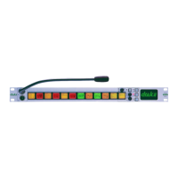
2.2.9 PD4225R/PD4225 Router Control Panel (2RU)
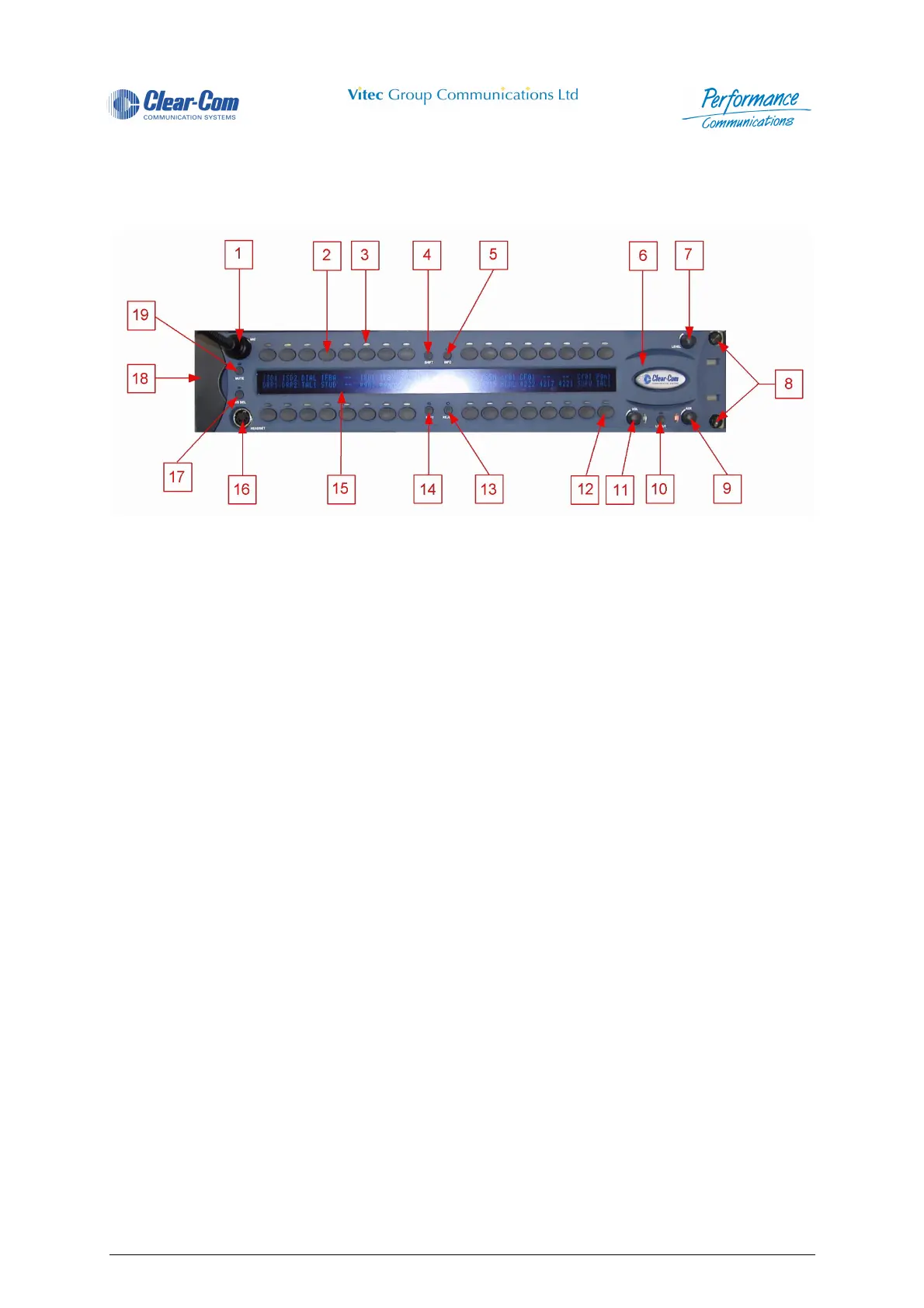
2.2.9.1 PD4225R Front View
Figure 18 - PD4225R Front View
1 Microphone Socket 11 Main Volume Control and Associated LED
2 Direct Access Key (DAK) 12 Reply Key
3 Indicator LED 13 Call Reject Pushbutton and Associated
LED
4 Shift Pushbutton and Associated LED 14 Soft Pushbutton and Associated LED
5 Info Pushbuttonand Associated LED 15 Vacuum Fluorescent Display (VFD)
6 Loudspeaker Aperture 16 Headset Socket
7 Crosspoint Level Control 17 Headset Select Pushbutton and Associ-
ated LED
8 Rack Mounting Screws (cover removed) 18 Cover Over Rack Mounting Points
9 Auxiliary Volume Control and Associated
LED
19 Microphone Mute and Associated LED
10 Loudspeaker Cut Pushbutton and Associ-
ated LED
 Loading...