4000 Digital Series II Issue 2.1 Technical Manual
STA0381 Page 5
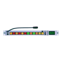
2.2.1.2 PD4215 Front View
Figure 2 - PD4215 Front View
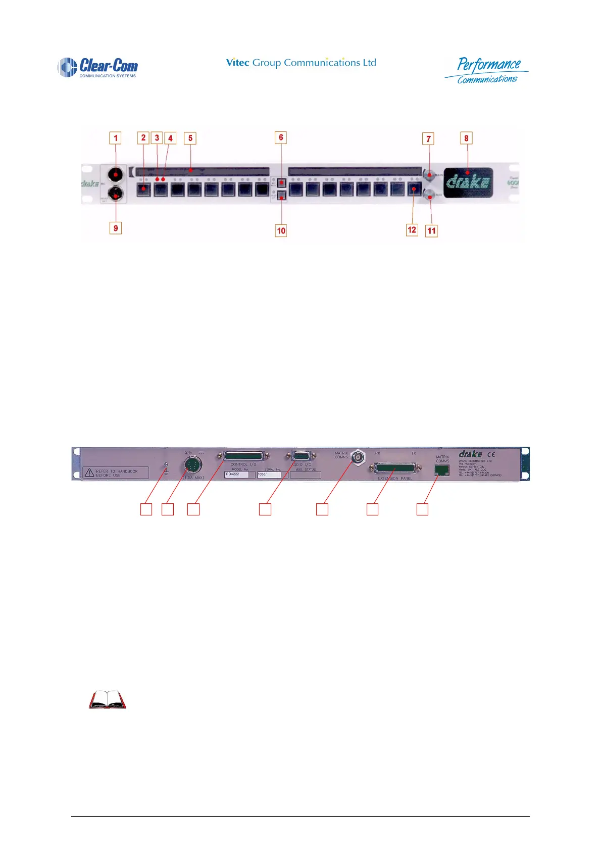
2.2.1.3 PD4215R/PD4215 Rear View
Figure 3 - PD4215R/PD4215 Rear View
1 Microphone Socket 7 Main Volume Control
2 Direct Access Key (DAK) 8 Loudspeaker
3 Talk Tally LED 9 Headset Socket
4 Listen Tally LED 10 Headset Select Pushbutton
5 Designation Strip 11 Auxiliary Volume Control
6 Microphone Mute Pushbutton 12 Reply Key
1 Earth Connection 5 Matrix Comms Connector (BNC) (Optional)
2 DC Power Connector (DIN) 6 Extension Panel Connector
3 Control I/O (Optional) 7 Matrix Comms Connector (RJ45)
4 Audio I/O (Optional)
For further information see the 4000 Digital Series II User and Installa-
tion Guides.
2 3 4 5 6 7 1
 Loading...