Technical Manual Issue 2.1 4000 Digital Series II
Page 84 STA0381
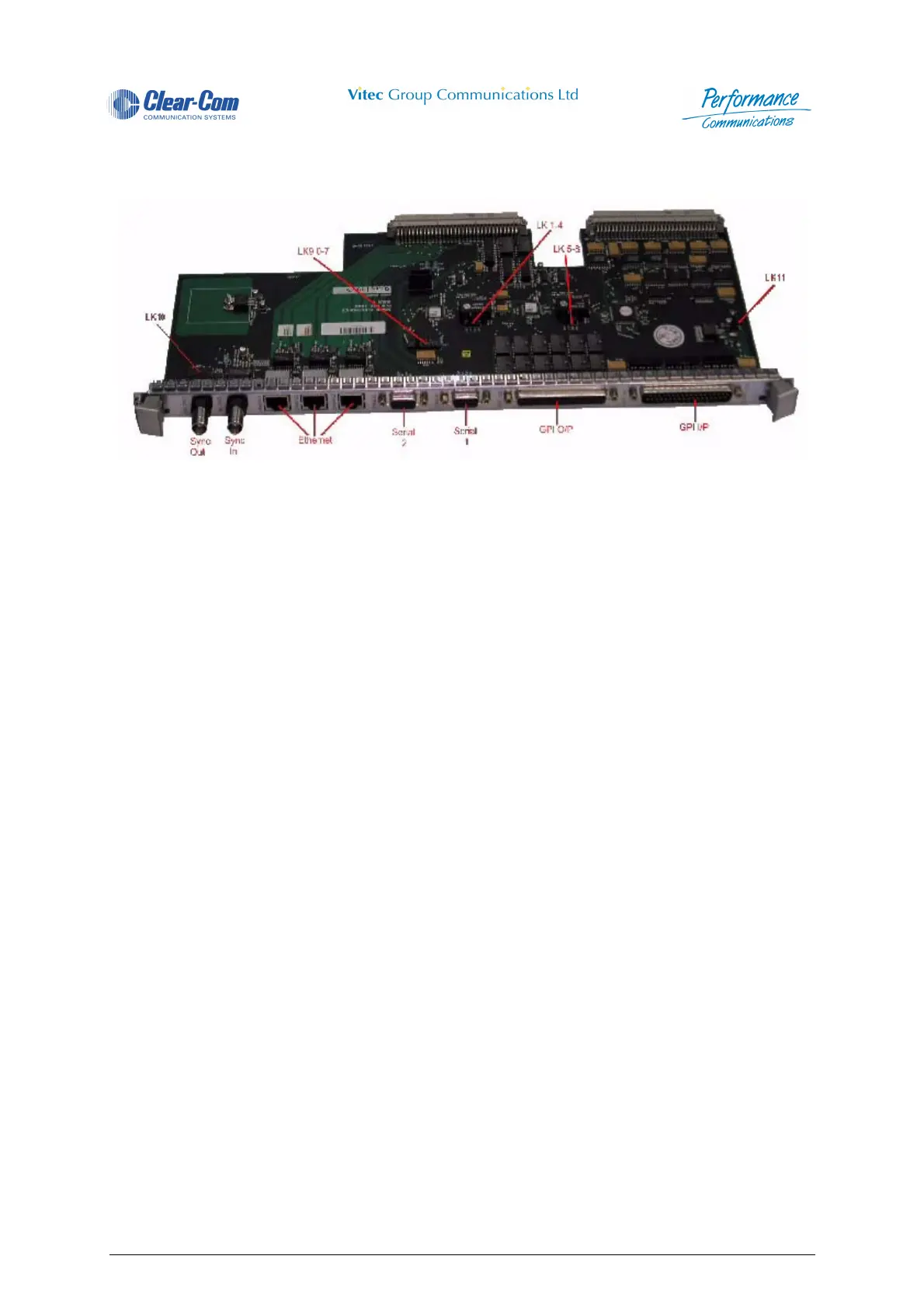
4.7 PDE4663 - Central processor RCU Card
Figure 80 - PDE4663 - Central processor RCU Card
The PDE4663 RCU provides connections to the RS232 (two 9-way socket D-type connector) ports
available on the Microprocessor cards (PDE4662). Only one RCU is required per matrix rack.
It provides three RJ45 Ethernet twisted pair connections. The main Ethernet network is normally
connected to Ethernet socket 2. If a second Ethernet connection is in use this is normally connected to
Ethernet socket 3.
Ethernet socket 1 is not used in normal operation.
Two BNC "sync" connectors provided are for synchronising different matrices together for future digital
trunk connections.
Two 37-way D-type connectors provide 12 GPI input and output connections.
The card also provides dual clock circuits with auto-fail detected and changeover if this happens. LEDs
D3 and D5 show which clock is the master.
4.7.1 Card location
One of these cards must be located in RCU slot 2 in the 4920 matrix, or RCU slot 1 in the 4420 matrix.
4.7.2 Links
Before fitting this card the links should be checked to ensure that they are correctly set for the
application. Details of the link settings are given below.
The links on the circuit card are as follows:
• Links LK 1 - 8 (in two blocks of four, see above). These links are factory set and should not be
adjusted.
• Links 3 and 7 are set, the remaining links are unset.
• Link LK9 (see above). These links selects the sample rate, as follows:
• 0 - 42.7 KHz (standard for Broadcast applications)
•1 - 32 KHz
• 2 - 25.6 KHz
• 3 - 21.3 KHz
• 4 - 18.3 KHz
• 5 - 16 KHz (standard for ATC applications)
 Loading...