Chapter 3. Installation
94
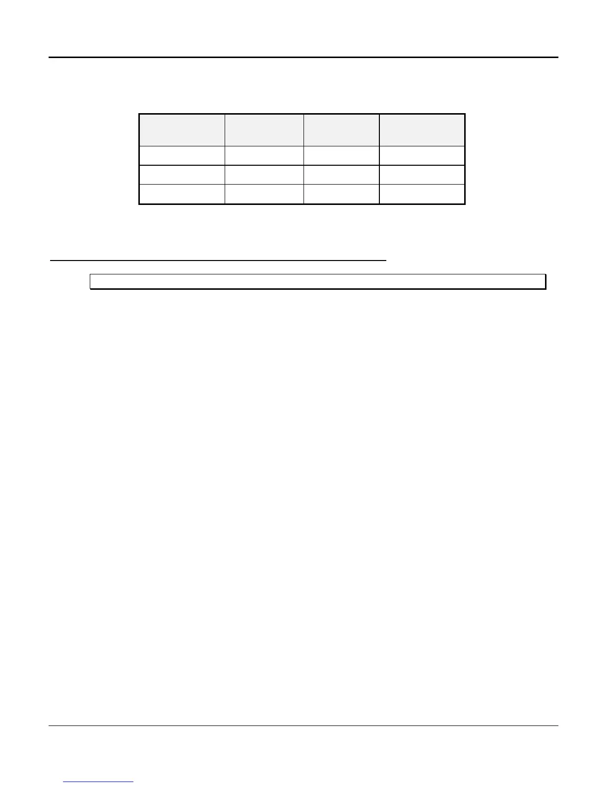
Table 3-15. Power Supply Fuses
(P/N 30338-102)
Fuse
Designation
Amperage Color Power Supply
Designation
GMT 1 1 Gray -48 AB
GMT 3 3 Blue -48 SB
GMT 4 4 White/Brown -48 DC
-48 V DC Power Supply Installation (P/N 30338-902)
Note: Do not fully seat the power supply until wiring and other common equipment is in place.
Following is the procedure for installing the -48 V DC Power Unit.
1. Place one DC Power Unit into the appropriate card slot for the shelf being powered
as follows:
• 8-slot: Card slot marked DC PWR, the second from the right card slot
• 12-Slot: Card slot marked DC PWR, the top middle horizontal slot, the bottom
of the card toward the left of the shelf
• 24-Slot: Card slot marked DC PWR, second card slot from the left on the
upper shelf
2. If a second DC Power Unit is to be used, place it in the second power supply card
slot as follows:
• 8-slot: Card slot marked AC/DC PWR, the first from the right card slot
• 12-Slot: Card slot marked AC/DC PWR, the top right slot, the bottom of the
card toward the left of the shelf
• 24-Slot: Card slot marked AC/DC PWR, first card slot from the left on the
upper shelf
 Loading...