Chapter 3. Installation
93
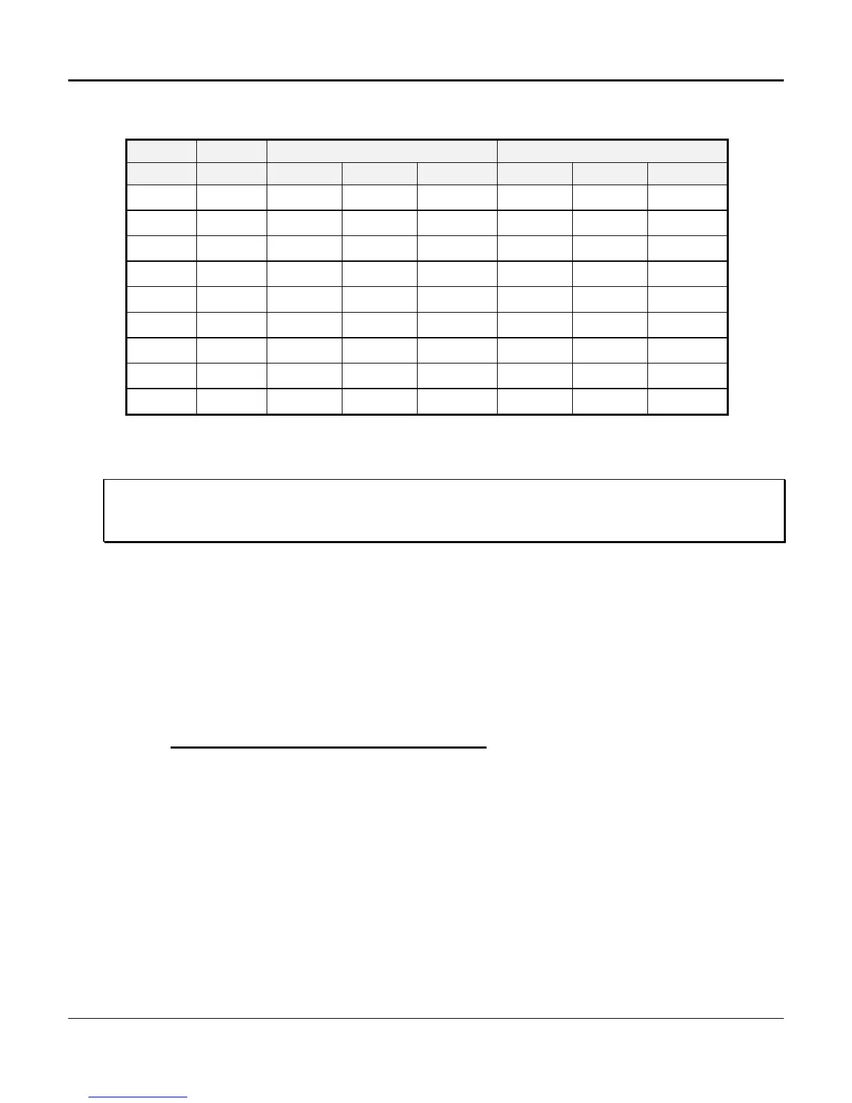
Table 3-14. Nominal/Maximum Power Consumption Matrix (W/BTUs)**
Chassis Shelf Fully Outfitted (Nominal) Shelf Fully Outfitted (Maximum)
(Slot) Voltage A W BTU/Hr A* W BTU/Hr
8 110 V AC 0.54 65 222 0.75 90 307
12 110 V AC 0.67 80 273 1.00 120 410
24 110 V AC 1.04 125 427 1.50 180 614
8 -48 V DC 1.25 60 205 1.77 85 290
12 -48 V DC 1.56 75 256 2.40 115 393
24 -48 V DC 2.50 120 410 4.16 200 683
8 -24 V DC 2.50 60 205 3.54 85 290
12 -24 V DC 3.12 75 256 4.80 115 393
24 -24 V DC 5.00 120 410 8.32 200 683
* Fusing Considerations: Fuse the main power to the selected shelf size at 150% of the maximum amperage indicated
in the column labeled “A” above. To allow for inrush current, select a slow-blowing fuse.
** Total power consumption depends on card type used in channel unit slots. Nominal refers to a fully outfitted shelf
with a typical combination of voice and data channel units. Maximum refers to a fully outfitted shelf with high
consumption data channel units. Maximum quiescent current for DC powered shelves includes consumption of
redundant power supplies.
-48 V DC Power Unit
(P/N 30338-102 and 30338-902)
Two -48 V DC power supplies can be used to provide redundancy; the additional power supply
plugs into a designated slot next to the first power supply. With redundancy, both power supplies
share the load; if one fails, the other assumes the full load. Either power supply can be inserted
or removed without interrupting service.
Test Points, Indicators, and Fuses
Front panel test points are available to monitor the various power input and output levels.
Three fuses are included with the -48 V DC power supply: Primary Power (-48 DC), Signal
Battery (-48 SB), and Alarm Battery (-48 AB). The ON LED indicator operates whenever -
48 V DC is supplied to the unit regardless of fuse or failure conditions. The FAIL LED
indicator illuminates when any power output is out of tolerance, or if a fuse is in
overcurrent protection mode.
 Loading...