Chapter 1. System Overview and Modes of Operation
38
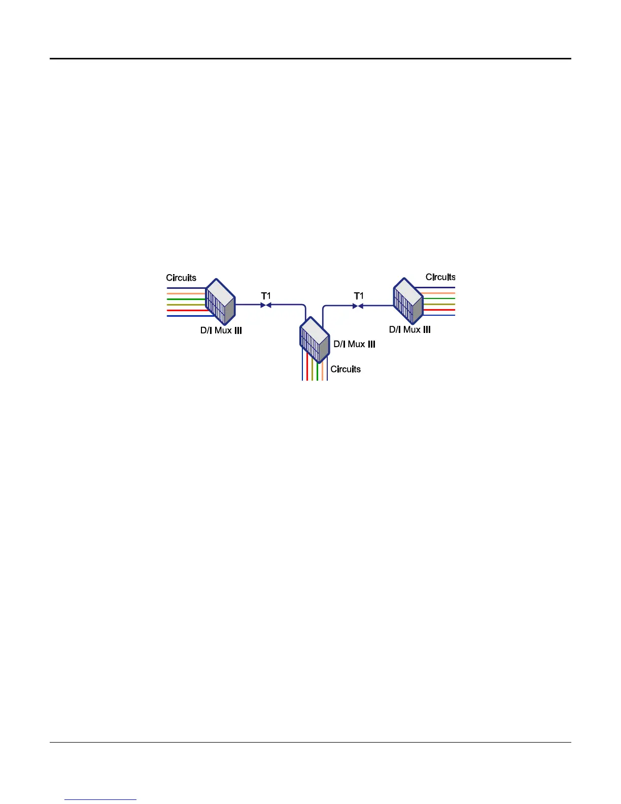
Drop-and-Insert Operation
In drop-and-insert operation a D/I Mux III connects two T1 transmission lines in a unique fashion, as
depicted in Figure 1-18. The D/I Mux III takes clock and DS0 channels from one T1 transmission port
and passes them through the system to the other T1 transmission port. Channels can be pulled from
(dropped), or placed on (inserted) the T1 line in either direction. The D/I Mux III line card circuits access
any of the 24 time slots in the DS1 signal. In drop-and-insert mode the system is always synchronized to
the network except during an alarm condition.
Any channels not accessed by the D/I Mux III in drop-and-insert mode are passed through digitally. This
unique multiplexing scheme introduces less than 20 ms of delay into the T1 line at each drop-and-insert
point.
In the event of a power outage in drop-and-insert operation, the T1 line bypasses the D/I Mux III
automatically, with a Dual DSX-1 interface installed. The Dual CSU interface requires -48 V DC to
operate.
Figure 1-16. Drop-and-Insert Operation
Recovered Timing
T1 basic timing is independent for each transmission direction in drop-and-insert mode, and is not
selectable. In this mode, both T1-1 and T1-2 clocks must be the same. T1-1 transmission timing
is provided by clock recovered from T1-2, and T1-2 transmission timing is provided by clock
recovered from T1-1. If one of the recovered clocks fails, the system can derive timing from the
internal clock or from the other T1 input. The choice of back-up clocks is software selectable.
Clock should not be present on both T1-1 and T1-2.
Dual Channel Bank Operation
In Dual Channel Bank (DCB) operation, a D/I Mux III terminates two T1 transmission lines. DCB mode
allows the system to synchronize with the T1 network (loop timing mode), or supply timing to the T1
network (local timing mode), as depicted in Figure 1-19.
DCB operation requires Line Interface Units (LIUs) (P/N 30309-104A and 30309-114A), which contain
“slip buffers.” In DCB mode the “slip buffer” LIUs align all clocks, bytes, frames and multiframes to one
common multiframe. T1 inputs and outputs are therefore synchronized to the same multiframe signal.
The “slip buffer” LIUs permit the T1 trunks of a D/I Mux III to operate in loop timing mode, recovering
clock from the network, or to be the source of network timing.

 Loading...