Chapter 1. System Overview and Modes of Operation
18
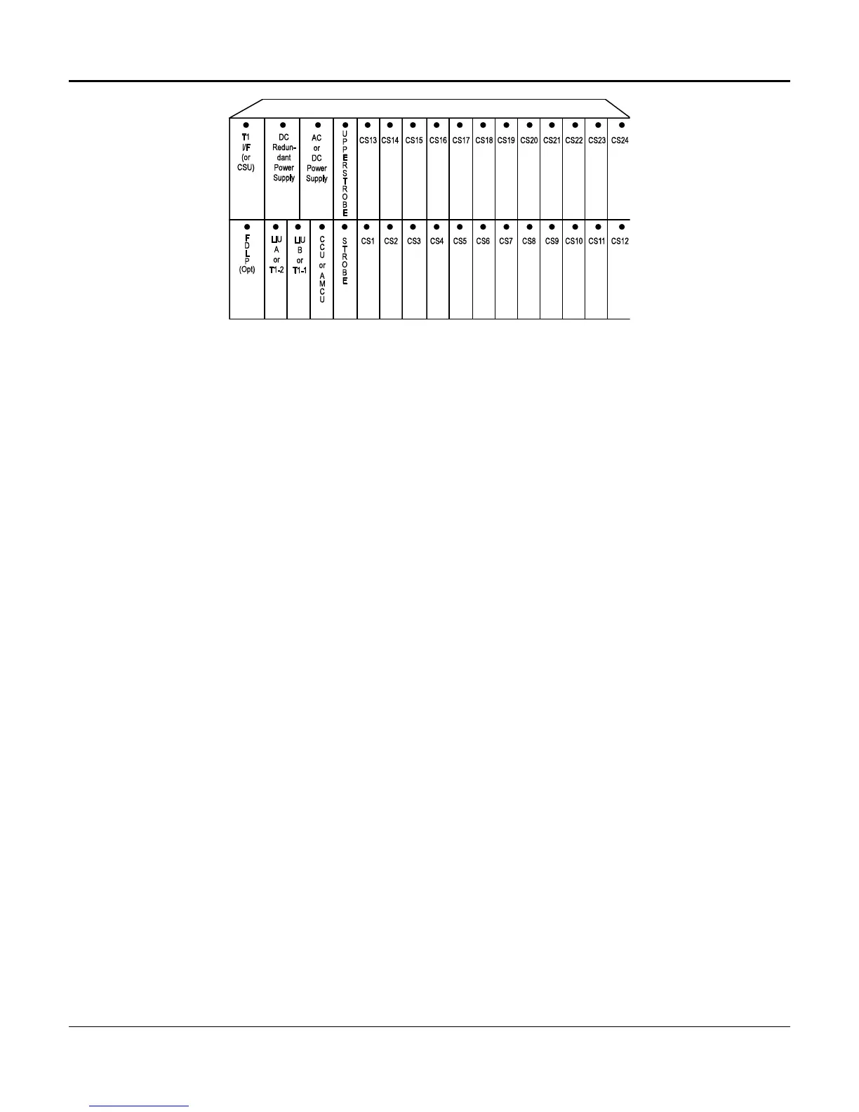
Figure 1-8. D/I Mux III 8-, 12- and 24-Slot Shelves
Shelf Backplane Connectors
A DB-9 female connector can be used as a synchronous input/output (Sync I/O) port to
synchronize the D/I Mux III with other systems. Both the synchronous output and the external
clock input are available on the DB-9 simultaneously. The Sync I/O provides an 8 kHz frame-
aligned Transistor Transistor Logic (TTL) output clock. The external clock input can be either a
single ended (TTL), or differential (V.35/RS-422) signal.
A DB-25 male connector is used for the COM port, which connects the system control terminal to
the D/I Mux III with an RS-232C cable.
The DB-25 male COM2 connector is reserved for future use.
The DB-25 female COM1 connector is used to connect a serial printer for a permanent record of
T1 transmission performance. It is only operational when a Facility Data Link Processor (FDLP)
is installed, and a network Line Monitoring Unit requests performance per AT&T Publication
54016.
DB-15 female connectors, or RJ-48 connectors, are used to connect to the T1 transmission lines.
Both connectors are wired in parallel for convenient selection. The T1-1 connector is used for
channel bank mode. Both T1-1 and T1-2 connectors are used for drop-and-insert, dual channel
bank, and ALPS modes.
Line cards connect to the shelf backplane via a 50-pin male Amphenol-type connector. DB-25
female connectors connect each card to the network. Jumpers select whether each card slot
uses the DB-25 or 50-pin connectors. For data applications, the D/I Mux III end of the cable must
have a male DB-25 connector. The opposite end of the cable will have the appropriate connector
to match the user's equipment.
The DB-25 connector always has voice/data on it when a line card is installed, even if the 50-pin
connector is being used. The VF/Data jumper should be in the VF position when using the 50-pin
connector.
See Figures 3-8 through 3-11 for backplane illustrations.

 Loading...