EasyManuals Logo

Coastcom D/I Mux III System User Manual

Coastcom D/I Mux III System
329 pages
To Next Page IconTo Next Page
To Previous Page IconTo Previous Page
Page #326 background imageLoading...
Page #326 background image
D/I Mux III User’s Manual Appendix I. Traps and Modem Dial Out Configuration
306
MODEM CABLE PINOUTS
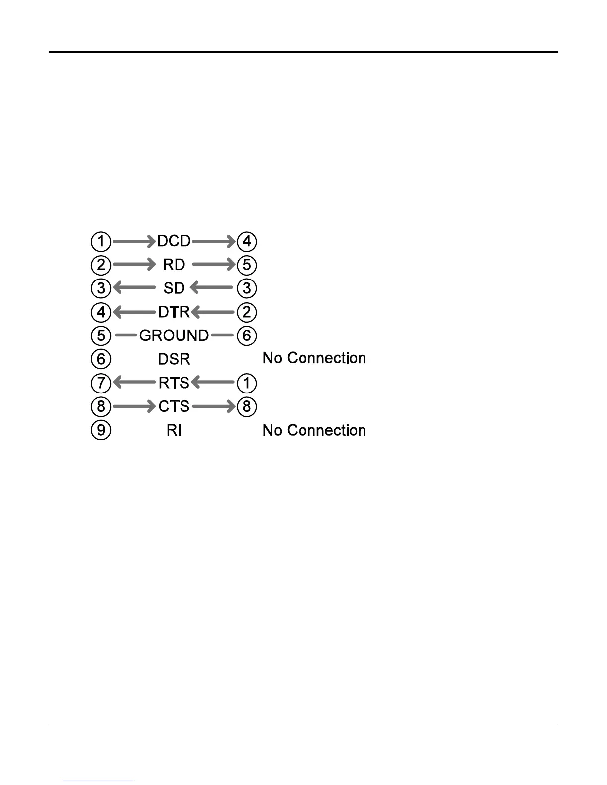
The table and diagram below show the pinouts for the cable that connects the AMCU with the modem.
The Modem end of the cable is a dB-9 connector, while the AMCU end is an RJ-45 connector (again this
is for a Hays modem, if the DB connector on your modem is different please consult your modem
manual)..
Modem end of cable AMCU end of cable
(Male dB-9) (Male RJ-45)
Figure J-19 Cable Pin Outs

Table of Contents

Questions and Answers:

Question and Answer IconNeed help?

Do you have a question about the Coastcom D/I Mux III System and is the answer not in the manual?

Coastcom D/I Mux III System Specifications

General IconGeneral
BrandCoastcom
ModelD/I Mux III System
CategoryMultiplexer
LanguageEnglish