D/I MUX III User’s Manual
ii
RELEASE NOTE August 2005
RING GENERATOR MODULE FOR D/I Mux III
Introduction:
The 30333-101 / 121 Ring Generator provides internally generated ringing voltage for AC or DC
powered D/I Mux III shelves with 2W FXS and Smart Omni-Orderwire feature cards. The
30333-101 is a –48 volt powered unit while the 30333-121 is a –24 volt powered unit. It provides
up to 15 watts of continuous, superimposed (ringing voltage referenced to the negative battery
supply voltage) sine wave ringing voltage. The nominal frequency is 20 Hertz. A front panel
green LED indicates the presence of power to the card. A red LED and relay contact closure
indicate generator failure.
Installation:
The 30333-101 / 121 Ring Generator can be installed in any of three available areas of the D/I
Mux III shelf: Power Supply, Feature Card or UCOM (FDLP). In any of the three locations, it
automatically configures itself to operate. It can be installed or removed while the shelf is in
operation (hot swapped).
When installed in the UCOM location the accessory 30333-101-UC cable must be in place on
the back of the shelf to complete installation.
Installation of 30333-101-UC cable. Note: this cable is installed only when the Ring
Generator is located in the UCOM (FDLP) card slot. This cable is included with each 30333-
101 or 30333-121 unit.
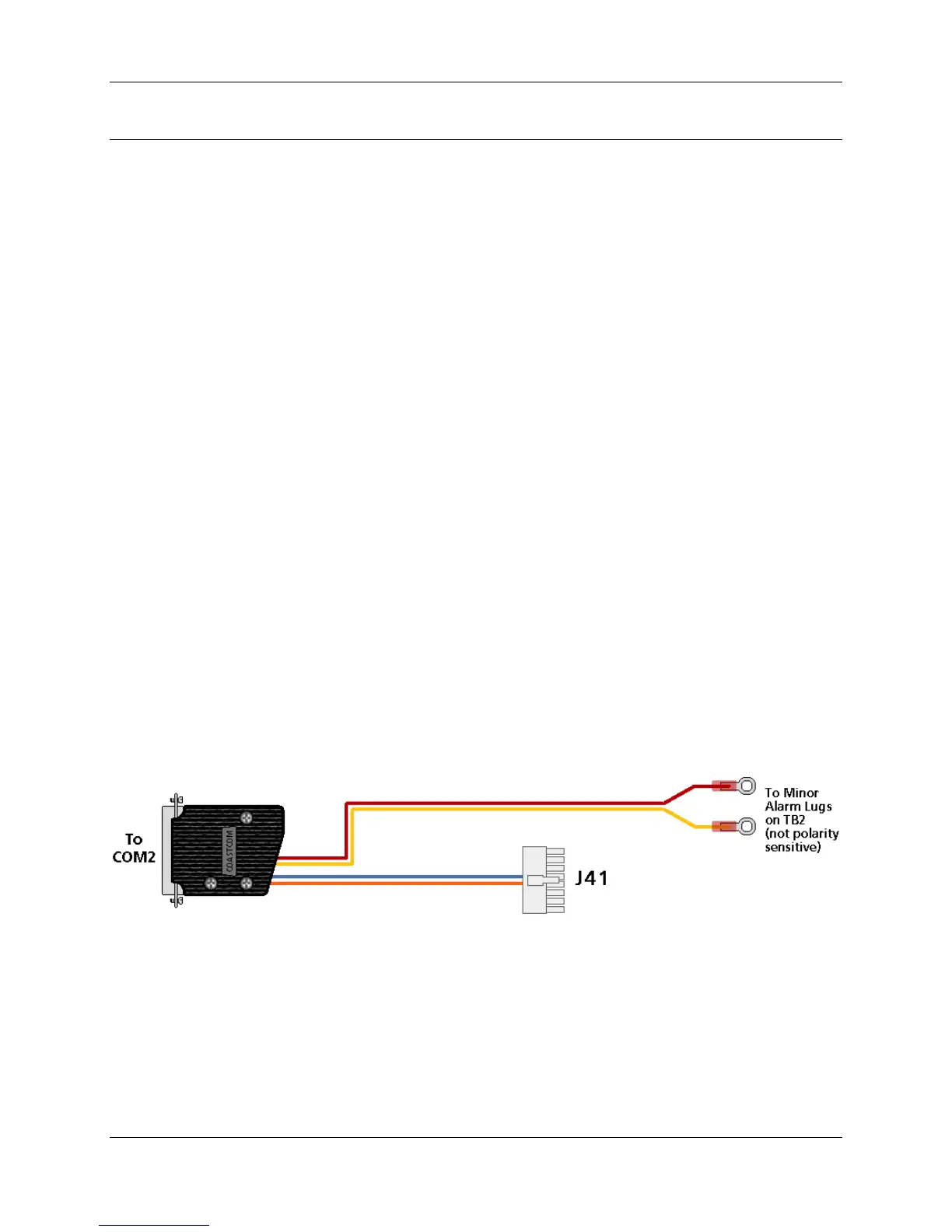
At the rear of the shelf, plug the 30333-101-UC cable’s DB-25 male connector into the
DB-25 female UCOM2 location. Plug the white Molex connector into the mating shelf
Molex connector marked “AUX SHF I/F”. Unscrew the two screws marked “MNR ALM”
on the screw-down barrier strip. Install the two cable wires with the ring lugs. Put one
under each screw head. Connections for failure alarm are made at this location on the
barrier strip.
DB – 25 – M MOLEX WIRE
AMP 205208-1 Shell 39-01-2160 18 AWG
AMP 66570-3 Pins w/39-00-0039 Insulated
AMP 206478-3 Hood Female Pins Hookup,
Pairs
Twisted

 Loading...