Chapter 3. Installation
71
50-Pin Voice Cable Installation
1. Locate the 50-pin VF connectors on the shelf backplane.
2. Connect VF lines to the 50-pin connectors.
3. Position the jumper above and below the data connector corresponding to each voice
card slot using the 50-pin connector. Place the jumper in the VF position.
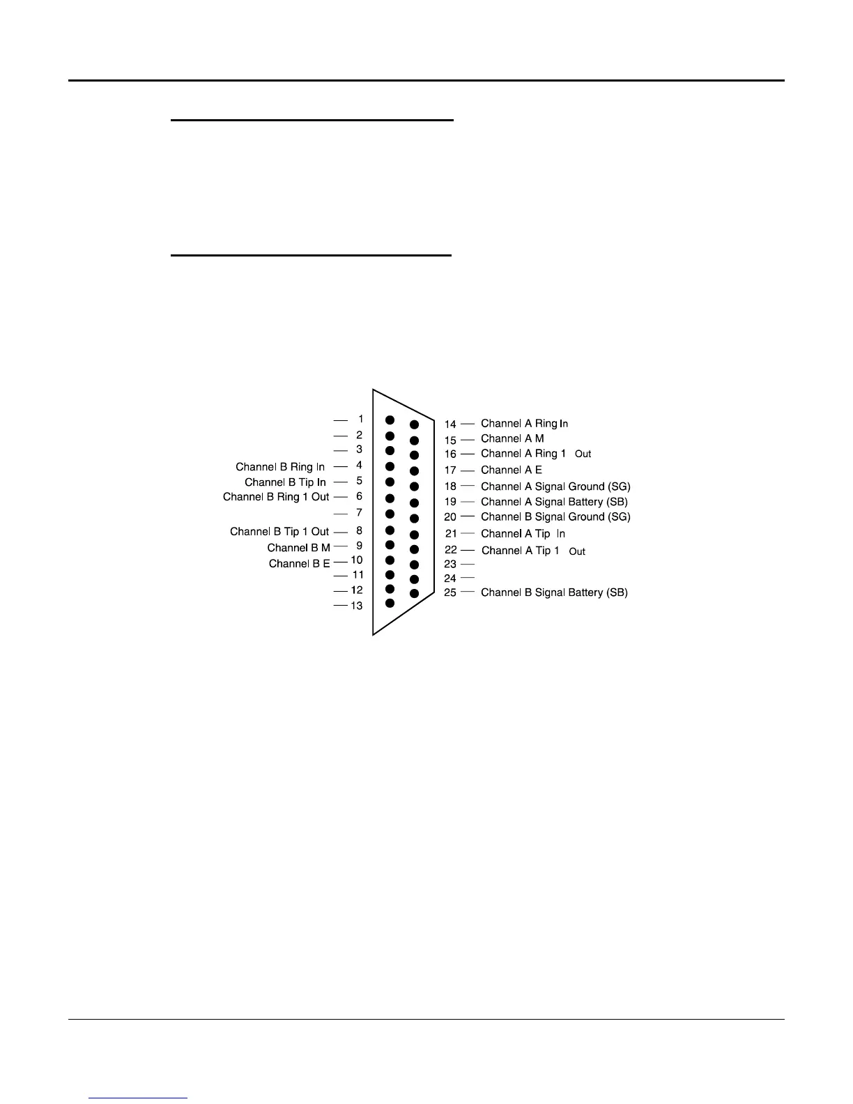
DB-25 Voice Cable Installation
The DB-25 data connectors can be used for voice connections which require Type II and
Type III signalling. The DB-25 connector pin-outs are shown in Figures 3-16 through 3-
20. Figure 3-16 shows the DB-25 pin-outs for single-channel (A only), and dual-channel
(A and B) voice line cards, while Figure 3-17 describes the DB-25 to wire-wrap
connections. Figures 3-18 through 3-20 detail connections for use with RS-232C,
RS-449 and V.35 interfaces respectively.
Figure 3-16. Single Channel, Dual Channel, and ADPCM
Voice Cards on DB-25 Female Connectors
 Loading...