ID–Lite-2.0 User guide, ©ComAp – January 2011 35
ID-Lite-2.0 User guide.pdf
Binary outputs
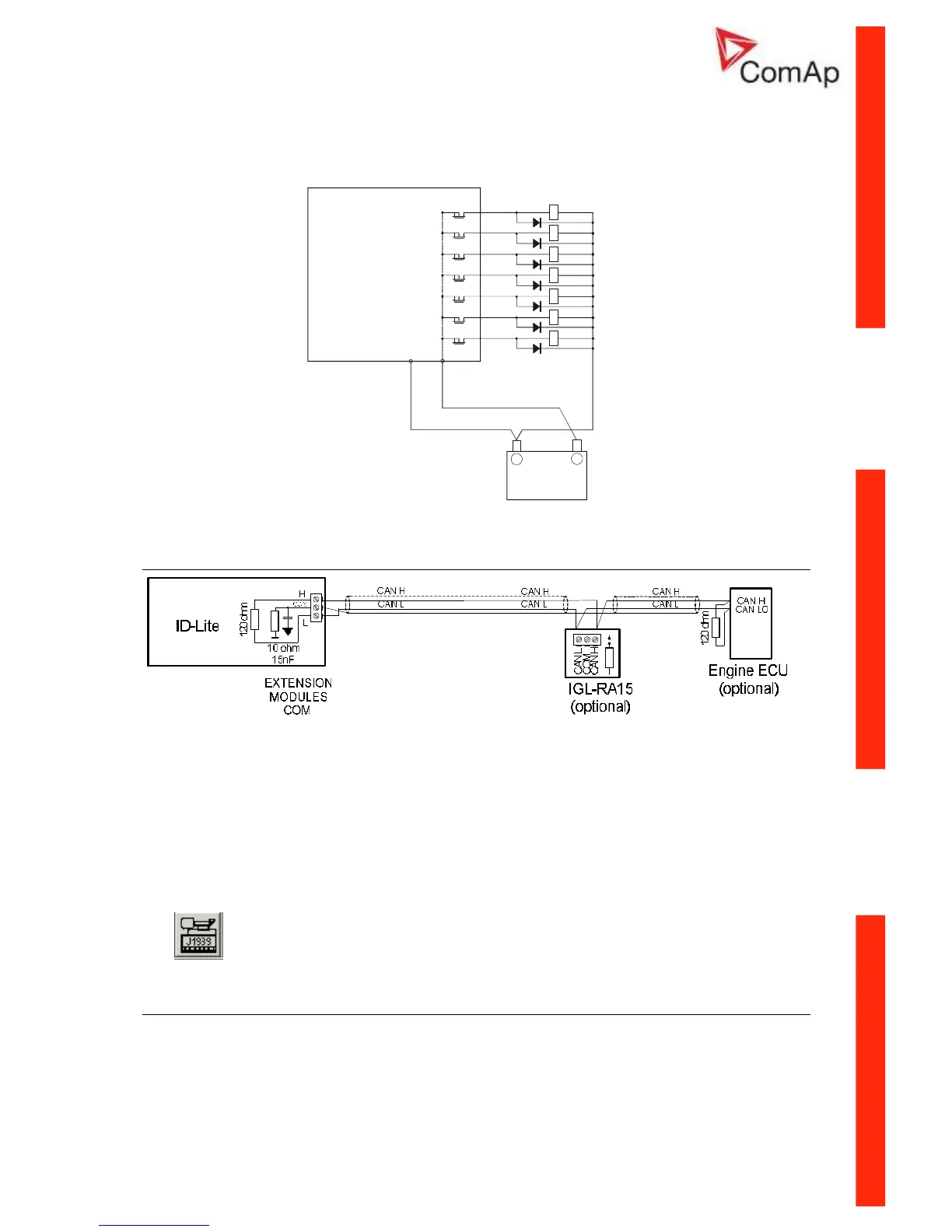
Extension modules - CAN bus connection
Connection rules
CAN bus line must be connected in series, from one unit to the next (no star, no cable stubs, no
branches) both ends must by the 120-ohm (internal or external) resistor terminated. Maximal CAN bus
length is up to 200 meters.
For CAN data cables details see chapter Technical data – Communication interface. CAN cable
shielding connect to ID-Lite COM terminal.
ID-Lite contains internal fix 120-ohm resistor and must be located on the CAN bus end.
It is possible to connect only one IGL-RA15 to ID-Lite.
Use button in LiteEdit (3.0 or higher) configuration window to activate CAN (J1939) interface.
Analog outputs
Optional plug in card IL-NT AOU8 provides eight Pulse-With-Modulation (PWM) outputs. These are
intended to drive VDO style analog gauges. This is to provide visual indication of typically ECU values
without installing additional sensors on the engine. PWM signal emulates sensor which would be
typically mounted on the engine.
Any value from controller may be configured to the outputs. Use LiteEdit PC SW to configure
corresponding sensor/gauge curve and value selection.