USER MANUAL FOR mPICO SERIES
Copyright - refer to title page
As shown in the above figure, the downlink BS signals go through DT port to the system and then to
downlink by duplexer separation. The DL signals will go through digital filter. Then the DL signals will be
sent to downlink PA to amplify power and filter via duplexer. After amplification, the signals are
transmitted at the MT port to the service antenna.
On the UL, the signals transmitted by the mobile go through MT integration duplexer and digital filer then
to uplink PA to power amplify and filter via duplexer, finally get back to BS by donor antenna.
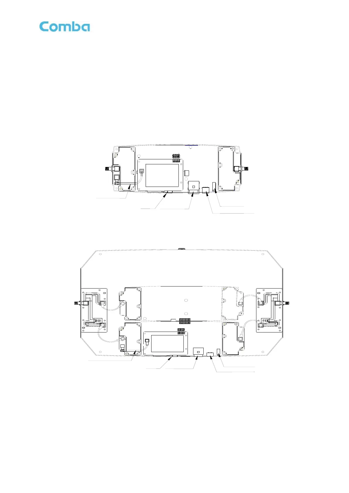
2.2 EQUIPMENT LAYOUT
The following figure shows mPICO internal layout.
Integrated
Module
Modem Jumper
USB
Modem
MT
DT
Power Connector
LED Indicator
Li-ion Battery Connector
Figure 5: Single Band mPICO Internal Layout
Base
Integrated Module(Master)
Integrated Module(Slave)
USB
Power
Modem Jumper
LED Indicator
Li-ion Battery
Combiner
Combiner
Modem
Figure 6: Dual Band mPICO Internal Layout