A
PPENDIX F-1
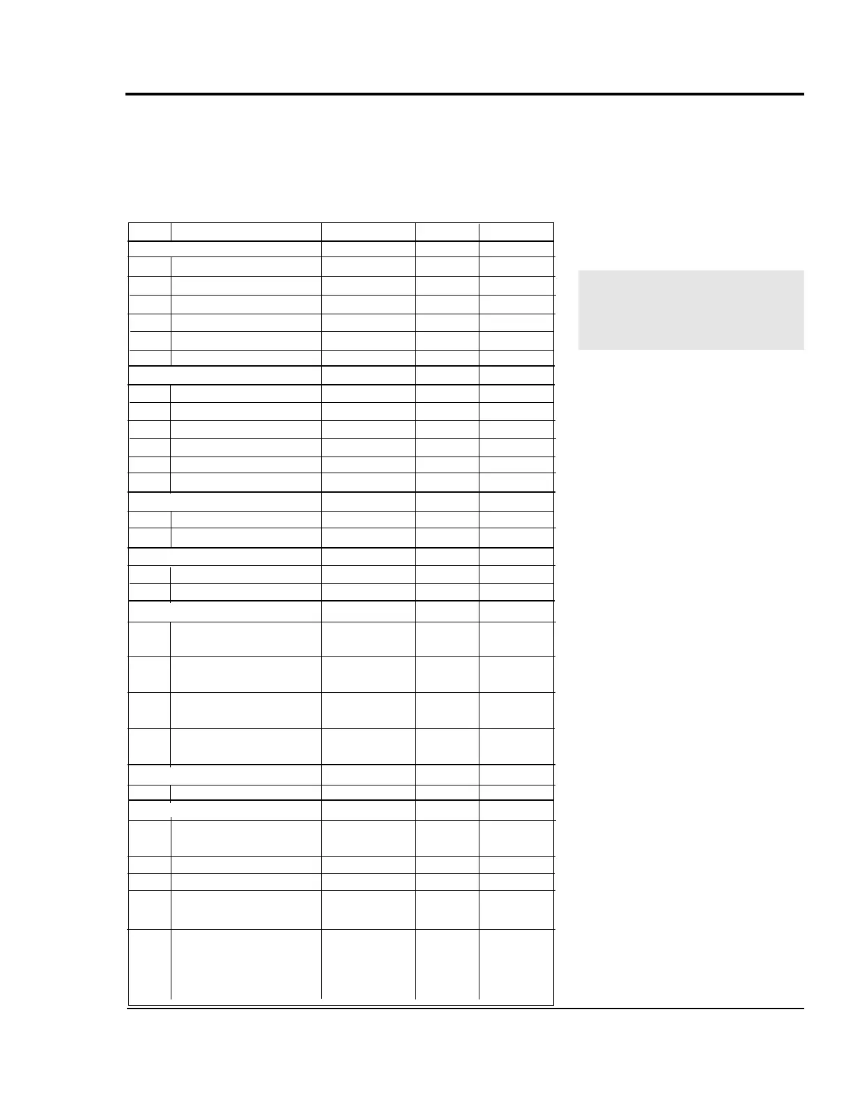
This table shows the settings for each control parameter set at
the factory. The parameters are set either to the default setting,
or to a setting specific to your requirements (Customer col-
umn). If you change any value, record it in this column. Keep
these values up-to-date so you can easily restore your puller to
normal operation if the memory is corrupted.
PULLER
CONTROL
S
ETTINGS
Code Parameter Range Default Customer
Setpoint Control
01 Primary Setpoint 1 0000-9999
02 Primary Setpoint 2 0000-9999
03 Secondary Setpoint 1 0000-9999
04 Secondary Setpoint 2 0000-9999
05 Jog Setpoint 0000-9999
06 Output Setpoint 0000-9999
Alarms and Limits
10 Minimum Limit 0000-9999
11 Maximum Limit 0000-9999
12 Low Alarm 0000-9999
13 High Alarm 0000-9999
14 Error Alarm 1, ramped 0000-9999
15 Error Alarm 2, scaled 0000-9999
Acceleration and Deceleration
16 Acceleration time 000.0-600.0
17 Deceleration time 000.0-600.0
Phase Control
18 Lag Pulse Limit 0-9999
19 Lead Pulse Limit 0-9999
Scaling
20 Engineering units 000.0-9999
(primary setpoint)
21 Engineering units 000.0-9999
(secondary setpoint)
22 Engineering units 000.0-9999
(primary display)
23 Engineering units 000.0-9999
(secondary display)
Phase Control
29 Recovery multiplier 0-100
Scaling
30 PPR (external 1-9999
reference input)
31 PPR (feedback input) 1-9999 60
32 PPR (auxiliary input) 1-9999
33 Max RPM (external 1-9999
reference input: primary mode)
34 Max RPM (feedback: 1-9999 1750
primary mode)
35 Max RPM (auxiliary 1-9999
input: primary mode)
If the control's memory is cor-
rupted by electrical noise or
static, you may need to reset
the control parameters.
UGE048/1103 PULLER CONTROL SETTING