5Electrical Installation Installation & Commissioning Manual
14
5100607_CFD5000 T - CM2.2_Installation & Commissioning Manual_T_EN_2023_F
The table below shows the minimum cable separation between the different cable
categories.
Table 2. Minimum cable separation distance in air.
Category A — Category B 0.1 m / 4 in
Category A — Category C 0.2 m / 8 in
Category B — Category C 0.1 m / 4 in
NOTE!
When different types of cables cross each other at right angle (90°), other limitations
apply.
If the minimum cable distance cannot be met, each category of cables must be
provided with metallic tubes, trays, screens, or similar in order to physically
separate them from other cable categories.
The preferred location of a loop cable is in the bundles for low voltage cables (such
as for alarm, communication, measuring and navigation equipment).
Shielding of cables
Although not a requirement, shielding of the detector loop cables is recommended
in order to protect them from electromagnetic emissions. Other cables of category
C should always be shielded, whereas category A cables could optionally be
protected. However in environments with exceptionally high electromagnetic
disturbance levels we strongly suggest that shielding is done for all cable
categories.
Shielding can be done by means of a screen or a conductive metallic casing around
the cable.
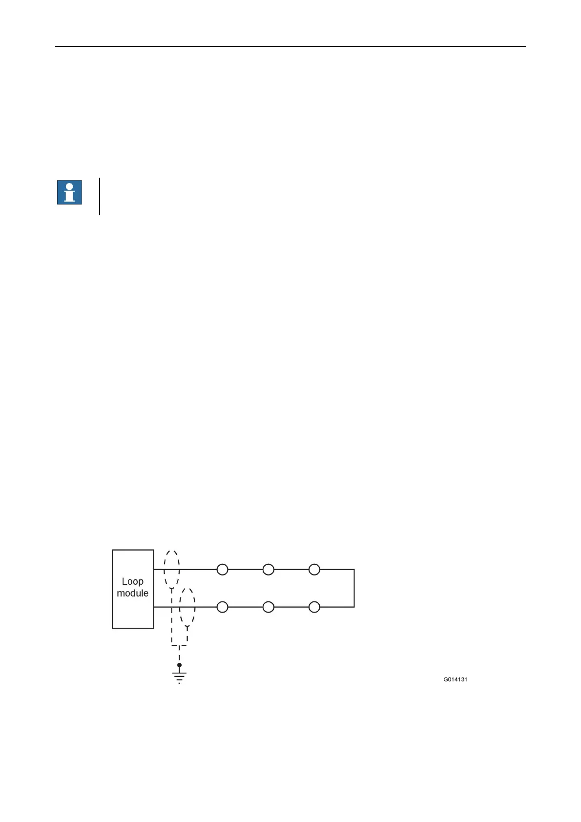
Earthing of cables
The earthing of the loop cables must be adapted depending on the design of fire
detection system (see examples below). This is to ensure that no currents run
through the screen due to voltage differences between the earth points (so called
stray voltage).
Figure 6. Earth points in a loop.