Installation & Commissioning Manual 12Appendix A
5100607_CFD5000 T - CM2.2_Installation & Commissioning Manual_T_EN_2023_F
81
12 Appendix A
12.1 ID List
12.1.1 Prerequisite
The ID switch must be set on the address unit type. The ID defines the function and
the type of the unit connected to the address unit.
12.1.2 Setting the ID
The ID is set by the 4-pole or 5-pole DIP switch located on the address units. The
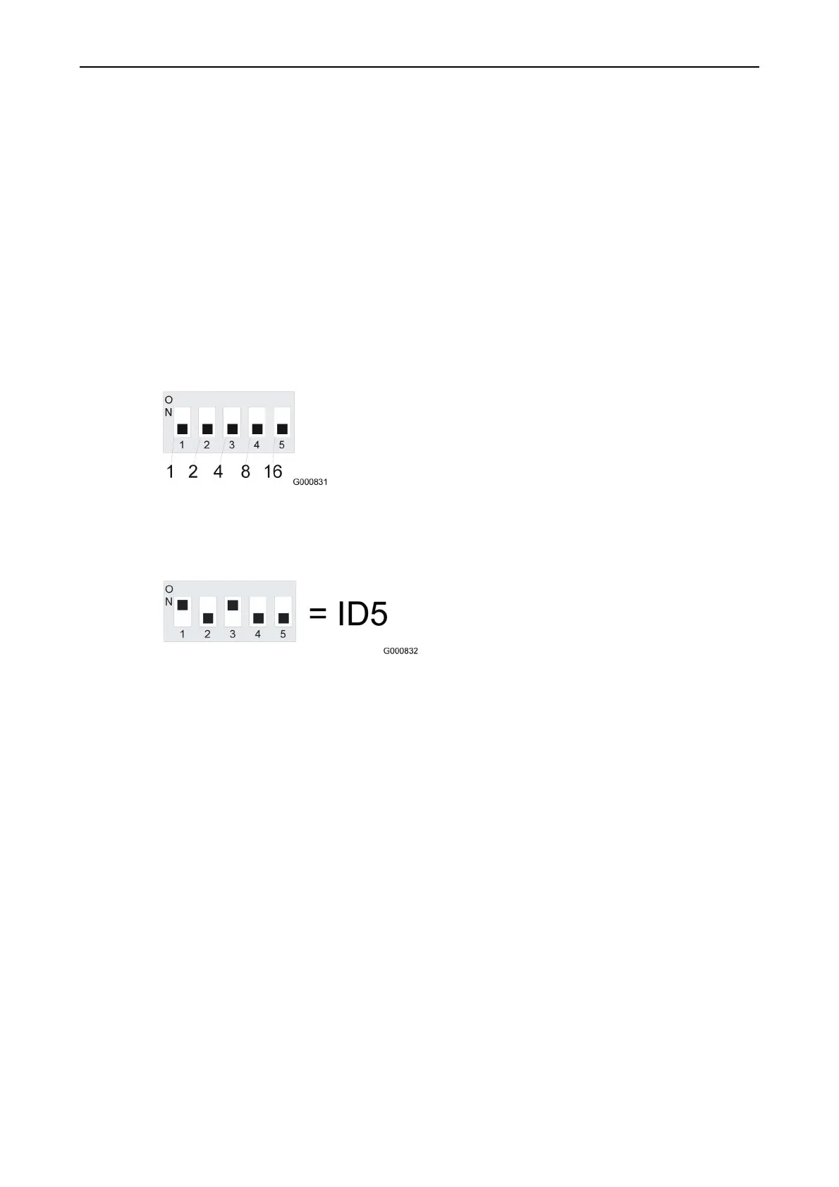
DIP switch value follows the binary system as shown in Figure37.
Figure 37. 5-pole DIP switch.
The value of the ID is according to the switches set to the “ON” position as shown
in Figure38.
Figure 38. Setting the 5-pole DIP switch.
The switches numbered 1 and 3 are set to the ON position. The values for these
switches are 1+4=5.
12.2 SSP termination
12.2.1 General recommendations for installation of
SSP
The SSP internal communication bus is a CAN based communication link between
modules CS-Loop M, CS-Safety M and CS-Com M.
General recommendations for SSP installation:
•
Termination shall be made at each end of the bus with a 120 ohm resistor.
•
When a CS-Safety modul is used, it must be placed at the end of the bus
because the CS-Safety modul has a built-in termination (120 ohm).