Installation & Commissioning Manual 6Mechanical Installation
5100607_CFD5000 T - CM2.2_Installation & Commissioning Manual_T_EN_2023_F
25
•
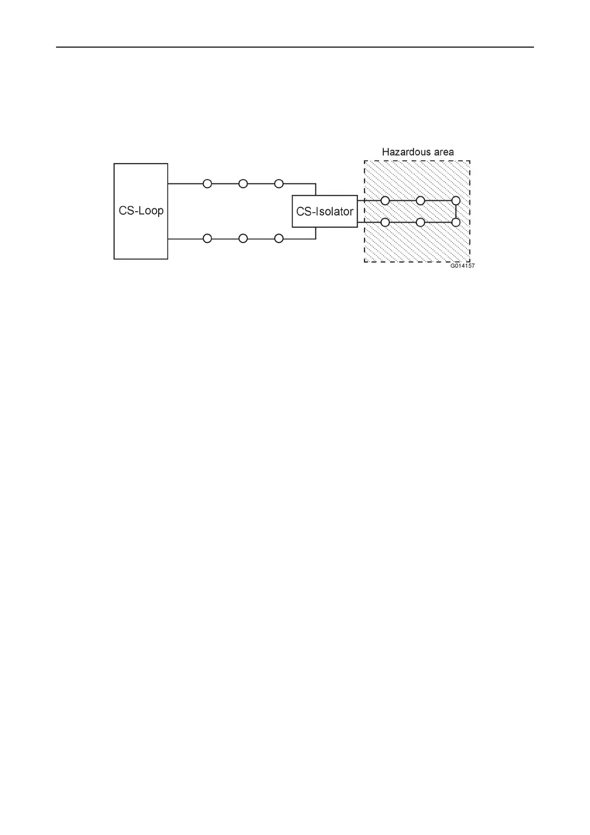
Detectors are connected to the fire detection loop through an isolator unit,
which must be located in a safe area directly outside of the hazardous area.
Install the smoke detector so it becomes easily accessible for service and
maintenance.
Figure 13. Example of IS circuit with loop units.
Installation in a hazardous area must comply with the standard IEC 60079-14
and/or the rules and regulations set by the local authority i.e. Class, National law
etc. Information regarding the intrinsic safety parameters can be found in the
control drawing for the detector type. Available is also the "Ex-Calculator" (Excel
spreadsheet) which can be used to verify the intrinsic safety of a circuit with regard
to the number and type of units, cable length, and gas group. Contact your local
supplier.
6.4.8 Line heat detectors
•
Connect the LHD to an address unit located in an environment suitable for the
address unit's IP class, and where it can easily be accessed for service and
maintenance. The maximum cable length between the end of the LHD and the
address unit is 25 m.
•
The address should be set on the address unit and the function ID switch (small
DIP-switch) should be set.
•
A suitable end-of-line resistor (refer to the data sheet) shall be fitted at the end
of the LHD cable.
6.4.9 Address units
•
The address unit is used to interface conventional detectors or any dry closing
contact to the addressable fire detection loop.
•
In addition to the loop address, the address unit has an ID switch that has to be
set. For more information, refer to ID List, page 81.
6.4.10 Manual call points
•
Positions where risk for impact or physical damage is likely to occur shall be
avoided.
•
In special category space.
•
A test key is supplied with each call point. Save these keys for future tests.