Installation & Commissioning Manual 5Electrical Installation
5100607_CFD5000 T - CM2.2_Installation & Commissioning Manual_T_EN_2023_F
15
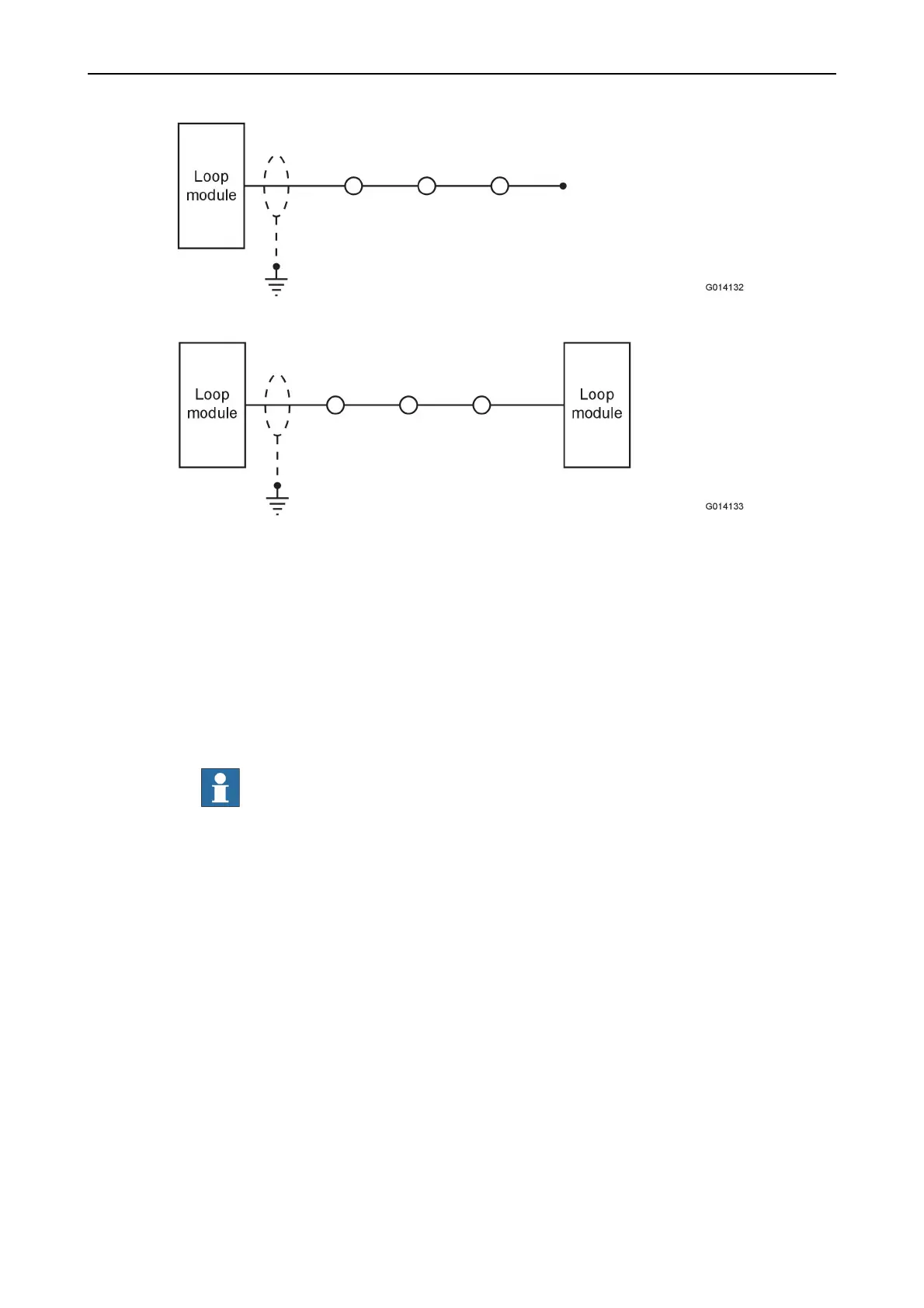
Figure 7. Earth points in a spur.
Figure 8. Earth points in a stretched central system (marine SRtP applications only).
5.2.2 Cable requirements
Backbone Bus External (BBE)
The cables connecting from the backbone bus to the control panels or stretched
central part must meet the following requirements:
Full redundancy (Channel 1 & 2 + backup signal)
•
Min 2 x 3 x 0.5 mm
2
, twisted pair shielded
•
RS-485 + backup signal, one single conductor
NOTE!
The backup signal is only needed for one channel. (The
backup signal is optional.)
•
Max allowed cable length is 700 m
Medium redundancy (Channel 1 & 2)
•
Min 2 x 3 x 0.5 mm
2
, twisted pair shielded
•
Max allowed cable length is 700 m
Low redundancy (Channel 1 + backup signal)
•
Min 1 x 3 x 0.5 mm
2
, twisted pair shielded
•
Backup signal, one single conductor
•
Max allowed cable length is 700 m