Installation & Commissioning Manual 5Electrical Installation
5100607_CFD5000 T - CM2.2_Installation & Commissioning Manual_T_EN_2023_F
19
•
Devices shall not be earthed by means of a separate earthing conductor through
another installation (serial earthing).
•
The door of a metal casing containing electrical equipment (voltage over 28 V)
must be earthed to the casings body with one earthing conductor. The earthing
fastening screw shall have a diameter of at least 6 mm with the exception of
the screws mounted by the manufacturer. The earthing screw shall not be used
for any other purpose than earthing.
•
Electrical equipment is to be earthed by a single conductor cable
(yellow/green) of supply cable with a cross section area of 1.5–16 mm
2
.
Other equipment earthings - see table below.
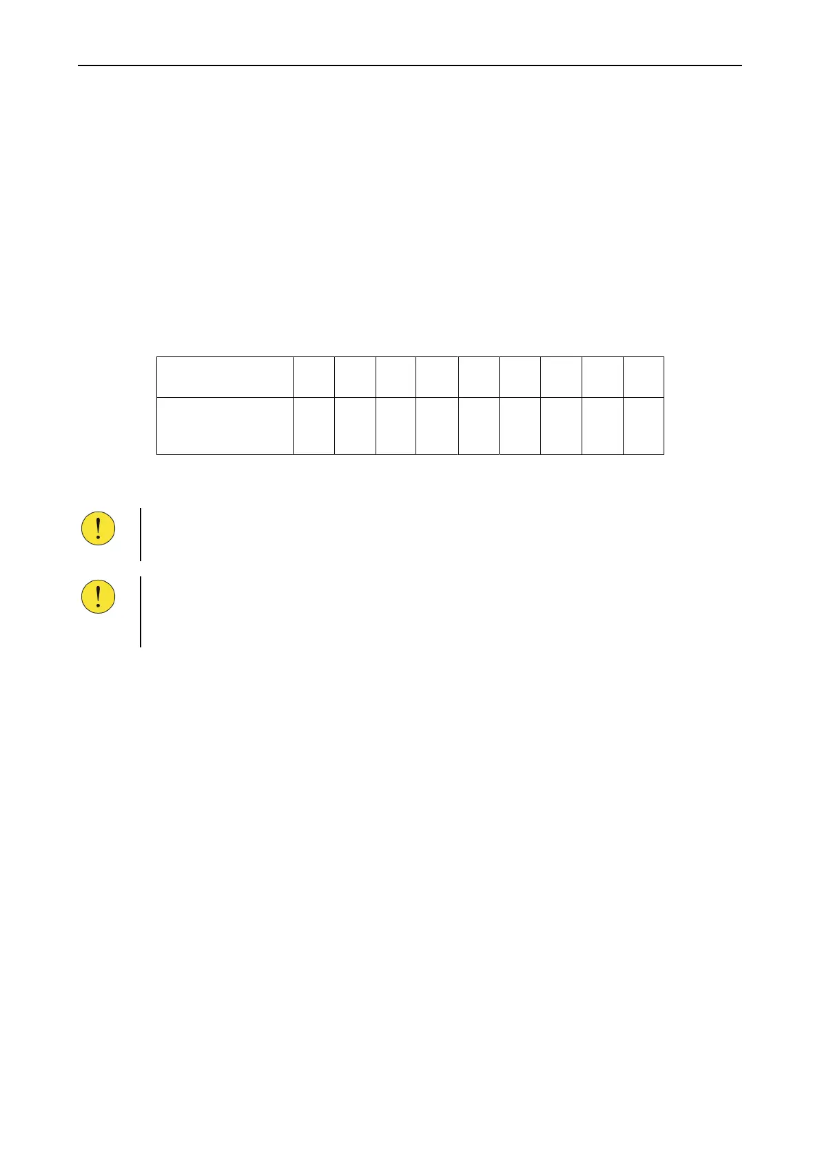
Table 3. Protective earthings for other equipment.
Cross section of supply
cable (mm
2
)
1.5 2.5 4 6 10 16 25 35 50
Single conductor cable
(mm
2
)
(yellow/green)
6 6 6 6 6 10 16 25 35
5.2.7 Location of electrical equipment
CAUTION!
Ensure that the central unit enclosure is installed in a location that satisfies its
environmental requirements specified in the drawings.
CAUTION!
It is highly important to eliminate or reduce any high external electromagnetic
interference which can have a negative effect on the loop communication.
Make sure that cabling is carried out according to international rules and regulations.
5.3 Electrical installation, central equipment
Terminal layout
For description of terminal layout please refer to project specific documents.