7Pre-commissioning Installation & Commissioning Manual
40
5100607_CFD5000 T - CM2.2_Installation & Commissioning Manual_T_EN_2023_F
•
Central cabinet
Verify that the Central cabinet is permanently mounted in its intended location.
•
External Control panel (where applicable)
Verify that the Control panel is permanently mounted in its intended location.
•
Repeater panel (where applicable)
Verify that the Repeater panel is permanently mounted in its intended location.
•
Printer (where applicable)
Verify that the printer is permanently mounted in its intended location.
Inspect the loop requirements/loop units
•
Loop cable requirements
Verify that the used loop cable meets the requirements according to the project
drawing.
•
Loop units
Verify that all base adapters/loop units are installed and connected according to
the datasheets and approved project drawings.
•
Address list and test report
Verify that the Address list and test report, page 79 are filled in and signed
according to Check the loop units, page 44. One set for each loop.
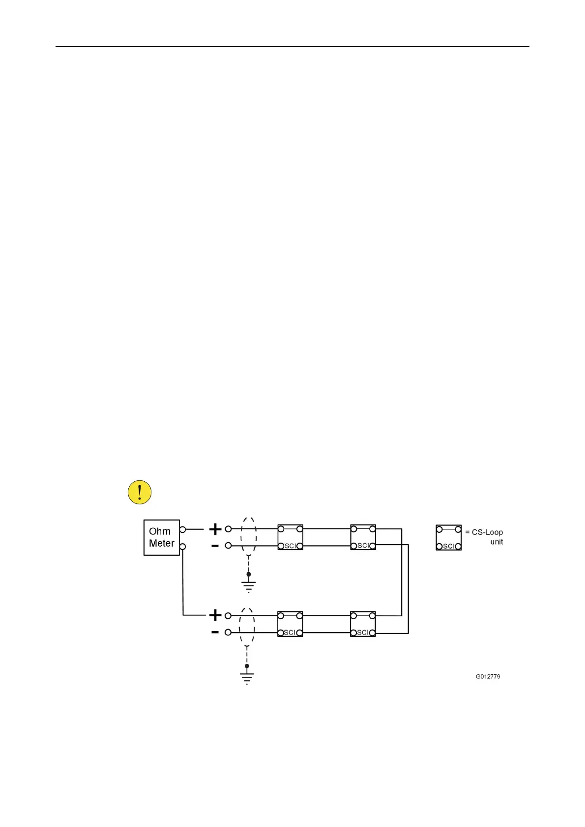
7.2 Test the loop cable
The loop cable should be tested for proper function after all the loop units are
connected and before the cable is connected to the loop module in the central unit.
A. Check the resistance of the loop-line
1. Connect an ohmmeter to the + poles on the loop-line.
CAUTION!
All loop units have a built-in short circuit isolator (SCI), therefore
always measure between the + poles.
Figure 26. Measure the cable resistance on the loop-line
2. Verify that the resistance is not above 53Ω.
Values above 53Ω would indicate either:
•
Too long cable length