Installation & Commissioning Manual 7Pre-commissioning
5100607_CFD5000 T - CM2.2_Installation & Commissioning Manual_T_EN_2023_F
41
•
Wrong type of cable
•
Loose connection
•
Cable break (infinitely high resistance)
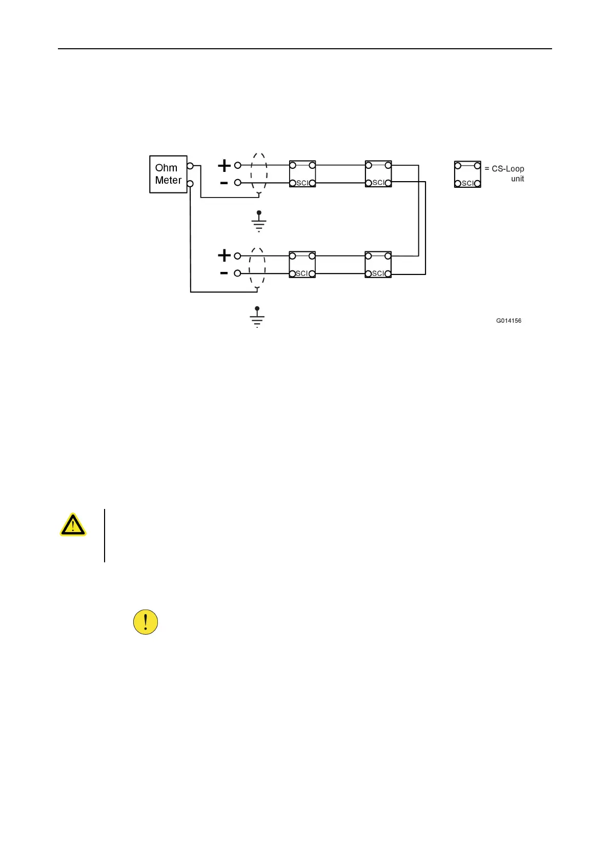
3. Connect an ohmmeter to the shielded poles on the loop-line.
Figure 27. Measure the cable resistance on the shielded part of the loop-line
4. Verify that the resistance is not above 150 Ω.
Values above 150 Ω would indicate either:
•
Too long cable length
•
Wrong type of cable
•
Loose connection
•
Cable break (infinitely high resistance)
B1. Test for cable break and short circuit in a non-hazardous
location/area
DANGER!
This test is only allowed in a non-hazardous location/area.
For installations in a hazardous (Ex-classified) location/area, please contact
Consilium for consultation.
1. Connect 24 VDC to the A-side of the loop-line according to Figure28.
2. Connect a voltmeter to the B-side of the loop-line according to Figure28.
CAUTION!
All loop units have a built-in short circuit isolator (SCI). It is important
to use a protection resistance 200 Ω to protect the SCI part.