7Pre-commissioning Installation & Commissioning Manual
42
5100607_CFD5000 T - CM2.2_Installation & Commissioning Manual_T_EN_2023_F
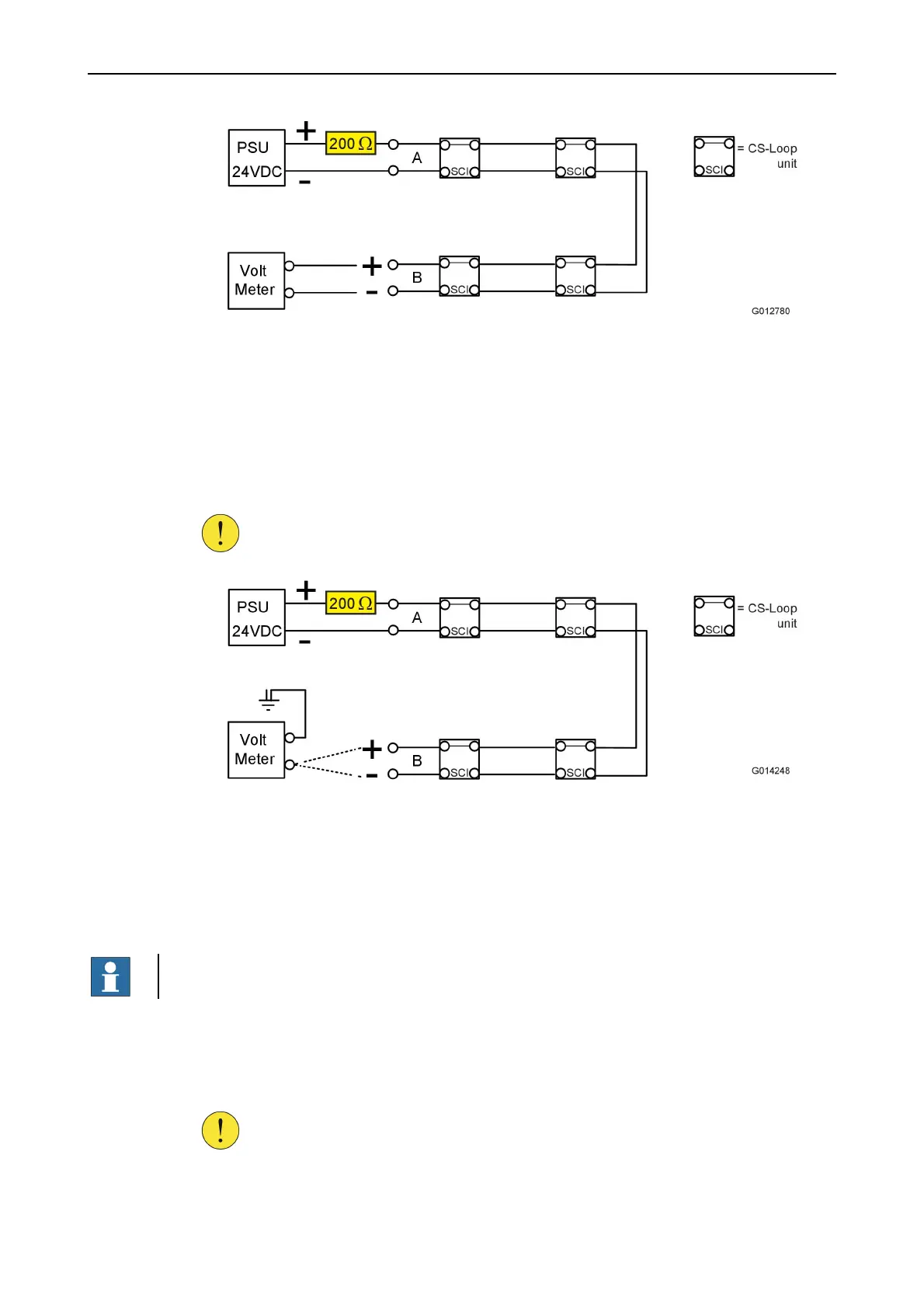
Figure 28. Measure the voltage with a voltmeter
3. Wait at least 2 minutes.
4. Verify that voltage is present at the B-side of the loop-line.
5. If the result from the step before was correct and the previous measurement according to
Figure27. has been verified, proceed to the next step.
6. Connect a voltmeter to the ground and measure the + pole respective the – pole on the
B-side of the loop-line according to Figure29.
CAUTION!
All loop units have a built-in short circuit isolator (SCI). It is important
to use a protection resistance 200 Ω to protect the SCI part.
Figure 29. Measure the voltage with a voltmeter
7. Values > 2 V indicates that there is a connection between shield and loop line and this will
result in an earth fault!
B2. Test for cable break and short circuit in a hazardous
(Ex-classified) location/area
NOTE!
Use this test for installations in a hazardous (Ex-classified) location/area.
1. Connect 24 VDC to the CS-Loop M module A-side of the loop-line before the CS-Isolator
unit according to Figure30.
2. Connect a voltmeter to the CS-Loop M module B-side of the loop-line before the
CS-Isolator unit according to Figure30.
CAUTION!
All loop units have a built-in short circuit isolator (SCI). It is important
to use a protection resistance 200 Ω to protect the SCI part.