Installation & Commissioning Manual 7Pre-commissioning
5100607_CFD5000 T - CM2.2_Installation & Commissioning Manual_T_EN_2023_F
43
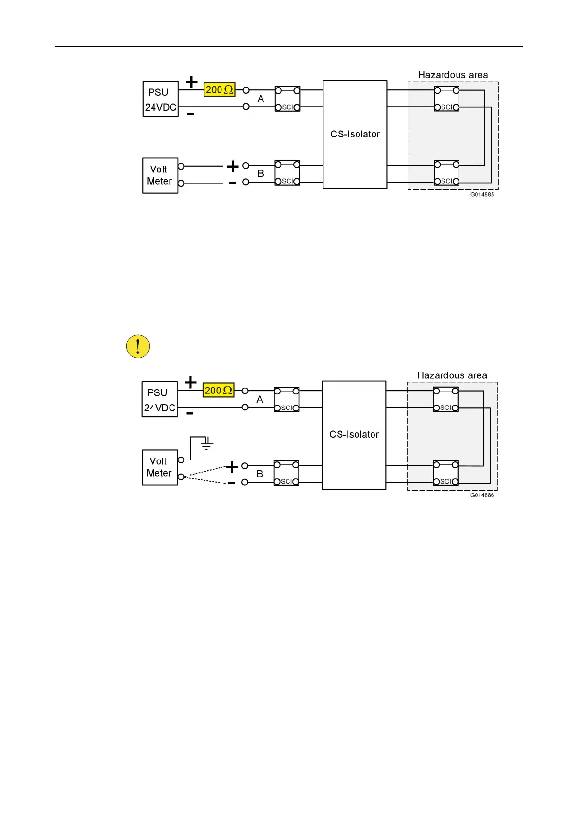
Figure 30. Measure the voltage with a voltmeter
3. Wait at least 2 minutes.
4. Verify that voltage is present at the B-side of the loop-line.
5. If the result from the step before was correct and the previous measurement according to
Figure27. has been verified, proceed to the next step.
6. Connect a voltmeter to the ground and measure the + pole respective the – pole on the
CS-Loop M module B-side of the loop-line before the CS-Isolator unit according to
Figure31.
CAUTION!
All loop units have a built-in short circuit isolator (SCI). It is important
to use a protection resistance 200 Ω to protect the SCI part.
Figure 31. Measure the voltage with a voltmeter
7. Values > 2 V indicates that there is a connection between shield and loop line and this will
result in an earth fault!
C. Test for earth fault on the shield
1. Connect an ohmmeter and measure the resistance between the shield and earth according to
Figure32.
 Loading...