EasyManua.ls Logo

Coretec BS Series - PIO Connector Pin Assignment; Wiring by the Side of Input

Default Icon
68 pages
Print Icon
To Next Page IconTo Next Page
To Previous Page IconTo Previous Page
Loading...
BS Controller for AC SERVO PRESS
Instruction Manual Ver1.08
BS-M3A-1B
- 27 -
6.9.2.
PIO connector pin assignment
A pin number, the wiring color of PIO cable, and a signal name are shown.
The shield line of a cable is connected to the connector shell by the side of a
controller.
ConnectorMOLEX54306-3611
Connector shellMOLEX54331-0361
CableSUN LIGHTSX 0.2×18P
PIN
No.
Bit
Color
Signal name
PIN
No.
Bit
Color
Signal name
1
I0
Gn
STOP
19
O0
LB/W
ALARM
2
I1
Br
RESET
20
O1
R/Bk
ALARM_MR
3
I2
Bl
ORIGIN
21
O2
Gn/Bk
READY
4
I3
Gy
START
22
O3
Br/Bk
IN_ORIGIN/BAT.ALA
RM
5
I4
Or
USER_SEL
23
O4
Bl/Bk
RUN
6
I5
Pr
JOG_SPD1/U_IN0
24
O5
Gy/Bk
OK
7
I6
Pn
JOG_SPD2/U_IN1
25
O6
Or/Bk
NG
8
I7
LB
JOG_ENA
26
O7
Pn/Bk
IN_JOG/AREA
9
I8
W
PNO1/JOG+
27
O8
LB/Bk
P_ANS1/U_OUT0
10
I9
Gn/W
PNO2/JOG-
28
O9
W/Bk
P_ANS2/U_OUT1
11
I10
Bw/W
PNO4
29
O10
Gn/R
P_ANS4/U_OUT2
12
I11
Bl/W
PNO8
30
O11
Br/R
P_ANS8/U_OUT3
13
I12
Gy/W
PNO16/U_IN4
31
O12
Bl/R
P_ANS16/U_OUT4
14
I13
Or/W
SERVO_ON
32
O13
Gy/R
U_OUT5
15
I14
Pr/W
U_IN2
33
O14
Or/R
U_OUT6
16
I15
Pn/W
U_IN3
34
O15
Pn/R
USER_SEL_ANS
17
R
+24V
35
Bk
0V
18
R/W
+24V
36
Bk/W
0V
6.9.3.
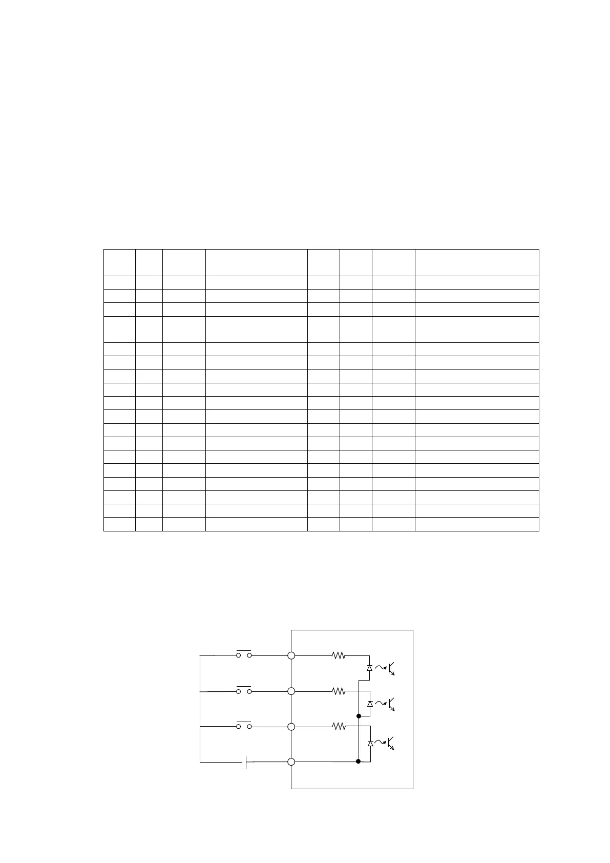
Wiring by the side of input
Common voltage is DC24V and serves as a photo-coupler input.Current is
about 5mA / 1 circuit.
BS
17,18
DC24V
IN
IN
IN

Table of Contents