BS Controller for AC SERVO PRESS
Instruction Manual Ver1.08
BS-M3A-1B
- 18 -
AC Power *10
AC200V 3φ
PLC
DC Power *10
DC24V
Emergency Stop *11
Servo Amp.
MR-J3-500A
BS Controller *3
BS-M3A-1B
BS100 Tool
Sequence cable
CCKSQ-3M *4
Parallel I/F cable *2
CBSPIF-**M
Serial Com. cable *2
CBS422-**M
Origin Sensor cable *1
CBSGS-**M
Load Cell cable *1
CBSLC-**M
Encoder cable *1 *8
MR-J3ENSCBL**M-L
Motor cable *1 *7
CBSMT10-**M
Brake cable
CBSBK-**M *1 *11
LAN cable(cross) *5
CCKLANC-5M
RS-232C cable
CCK232-3M *9
FA Network
Board
Application software
Regen. Reg. *12
MR-RB31
MR-RB51
PC
LED Display
LDS-24
LED Display cable
CCKDSP-**M *6
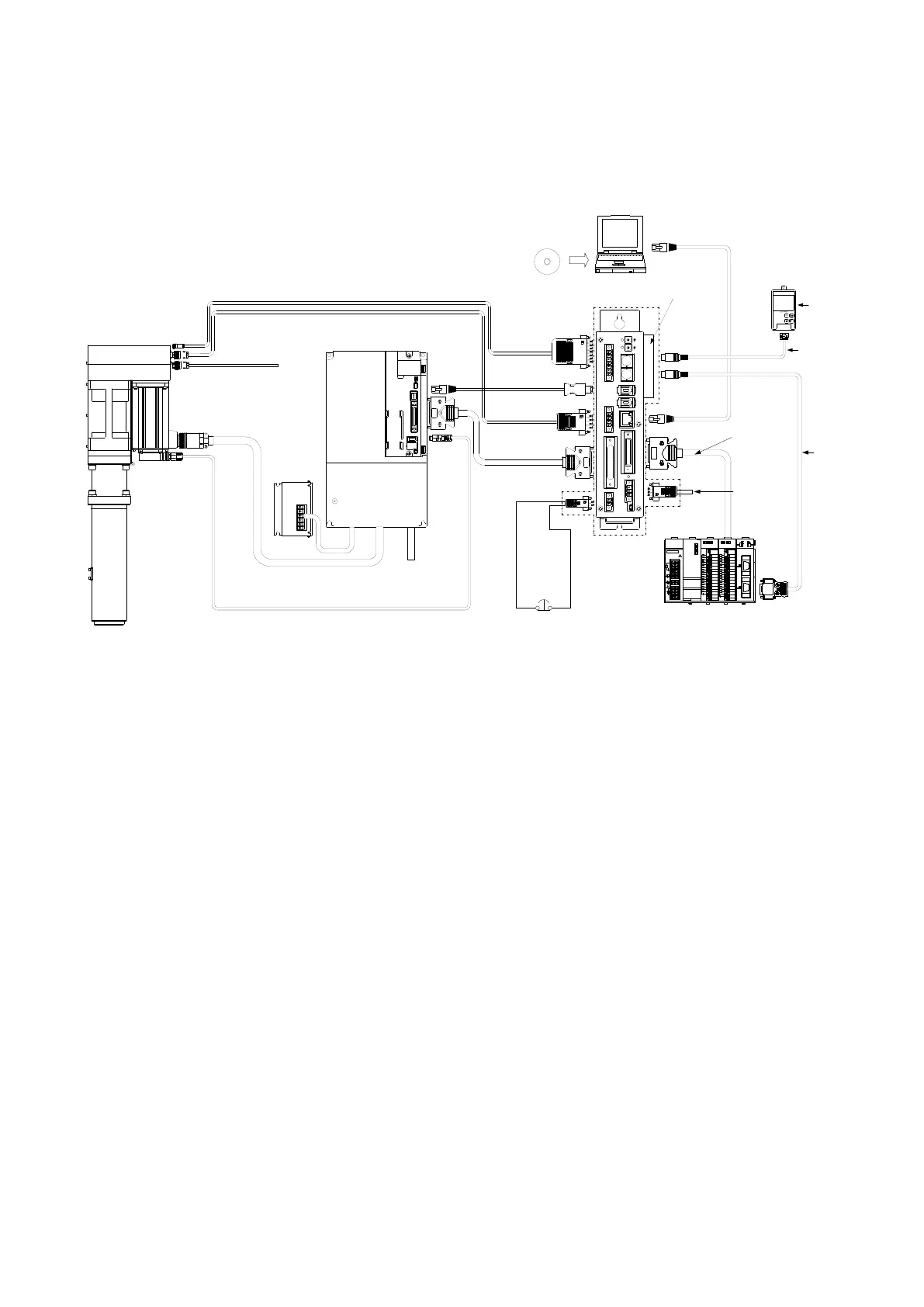
Connection figure (include options)
4.3.1.
Fig.4-3-1 BS100 Series
*1 The length of a cable is selectable from 5,10 and 20m. The junction cable is not
prepared.
*2 The length of a cable is selectable from 0.5 and 1m.
*3 The connectors in a dashed line are included to the controller set.
*4 This is unnecessary when using a FA Network Board.
*5 The type of LAN cable may not be crossing when using a HUB.
*6 The length of a LED Display cable is selectable from 5 and 10m.
*7 The model name of movable cable is CBSMT10R-**M.
*8 The model name of movable cable is MR-J3ENSCBL**M-H.
*9 Detail of the model name is different for each PLC type.
*10 A customer prepares cables.
*11 A customer controls this line.
*12 A external regeneration resister is an option.