1 - General 5
Explanations
P = processor board
C = connector board
RS232 = Standard defining communication between a computer and the COROB
TM
D300
PULSE = Pulse sensor
ZERO = Zero sensor
CUP = Humidifier cap sensor
M1 = Dispensing motor
A = Interface board for valves
B = Interface board for pumps
C = Interface board for stirring motors
M = Stirring motors, 16 pieces
The sensors are connected to the connector board that transmits information to the processor
board and to the PC.
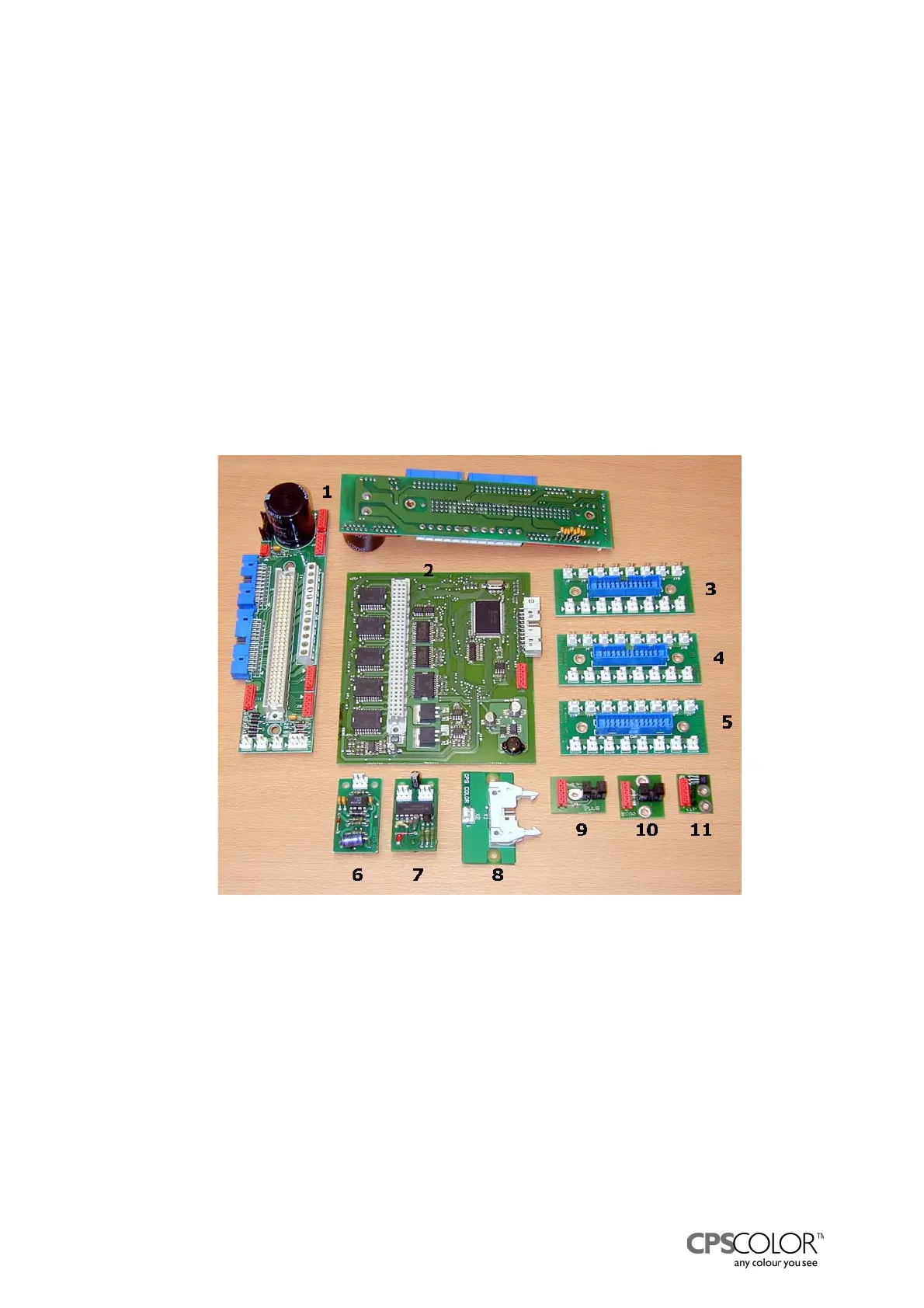
All boards that are in the COROB
TM
D300 are shown in figure 7. The order code for each board is
after the name of the board in table 3.
Table 3. Boards in figure 7
1. Connector board
(V44752) 2. Processor board (V43786)
3. Interface board C: Stirring (V44846)
4. Interface board B: Solenoids for selecting the pumps (V44844)
5. Interface board A: Solenoids for opening the valves (V44845)
6. IR receiver board (V06271) 7. IR transmitter board (V06270)
8. Cable interface (V44971) 9. Pulse sensor (V43769)
10. Zero sensor (V43773) 11. Humidifier cap sensor
(V43676)
Figure 7: Boards of COROB
TM
D300