6 1 - General
COROB
TM
D300
The COROB
TM
D300 has three interface boards: A, B and C. The boards A and B are for controlling
solenoids. The solenoid board A that controls the valves is in front of the dispensing module, in the
lower part of it, see number 8 in figure 5. The other solenoid board, board B, is in the solenoid rail
assy behind the dispensing module, see figure 9. The pump or the pumps that are going to
dispense are selected with this board.
Movement of the impellers of the colorant canisters are controlled with the interface board C.
There is a stirring motor under each colorant canister. This motor rotates the impeller inside the
canister. The interface board C is on the right side of the canister rack, it’s marked with letter C in
figure 3 on page 3.
The locations of the sensor boards are marked in figure 71 on page 32. The cable interface is on
top of the can table, see number 10 in figure 5 on page 4.
Solenoids
The COROB
TM
D300 has 33 solenoids, two different sizes:
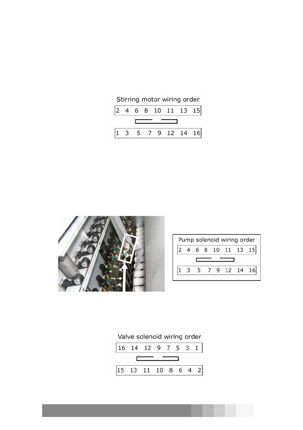
• sixteen smaller ones for selecting the piston of the pump. These solenoids are behind the
dispensing module. The wiring order to solenoids from the board is described in figure 10.
• sixteen bigger solenoids are for opening the valves. The solenoids are in front of the
dispensing module. The wiring order from the board to the solenoids is described in figure 11.
Figure 8: The wiring order to stirring
motors on the interface board C.
Figure 10: The wiring order on the
interface board B.
Figure 9: Interface board B is fastened to the
solenoid rail assy behind the dispensing
module.
Figure 11: The wiring order on board A,
which controls the movement of the valves.