68 • 4-Series™ Control Systems Product Manual — Doc. 8559B
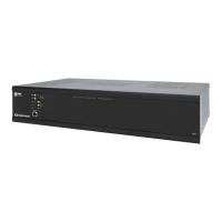
COMPUTER
(front)
(1)USBType-B connector, female;
USB2.0 computer console port;
For setup only
LCD Display
Display Type TFT active matrix color LCD
Size 2.8in. (72mm) diagonal
Resolution 320 x 240 pixels
Functions Displays configuration menus, control port activity, and other system
information
Controls and Indicators
PWR (1) Bicolor green/amber LED, indicates operating power is present;
Amber indicates that the device is booting and is not yet ready to operate;
Green indicates that the device is ready to operate
NET (1) Amber LED, indicates communication with Cresnet devices
MSG (1) Red LED, indicates control processor has generated a logging message
HW-R (1) Recessed push button, initiates a hardware reset
SW-R (1) Recessed push button, initiates a software reset
CNPSFAULT (1)Red LED and (1) push button;
LEDindicates an excessive Cresnet load is detected at the NETport;
Push button resets the fault indication
SLOT1–3 (3)Green LEDs, indicates control cards are present in the corresponding rear
panel slots
Nav Pad (1) 5-way navigation pad for LCD display menu navigation and parameter
adjustment
HOME (1) Push button, returns to the LCD display home menu
BACK (1) Push button, returns to the previous screen on the LCD display
LAN (1) Bicolor green/amber and (1) amber LEDs;
Green/amber LEDindicates Ethernet link status and connection speed;
Amber LEDindicates Ethernet activity
CONTROL
SUBNET(rear)
(1) Bicolor green/amber and (1) amber LEDs;
Green/amber LEDindicates Ethernet link status and connection speed;
Amber LEDindicates Ethernet activity
Power
Main Power 2.4A@100–240VAC, 50/60Hz
Power over Ethernet
Plus (PoE+)
IEEE 802.3at compliant PoE+ PSE (Power Sourcing Equipment);
120W total power;
Each CONTROL SUBNET port supplies up to 30 W to power one PoE+ (Class 4)
PD (Powered Device)
Available Cresnet Power 75W (3.125A@24VDC)