78 • 4-Series™ Control Systems Product Manual — Doc. 8559B
Observe the following when connecting the control system:
l
Use Crestron power supplies for Crestron equipment.
l
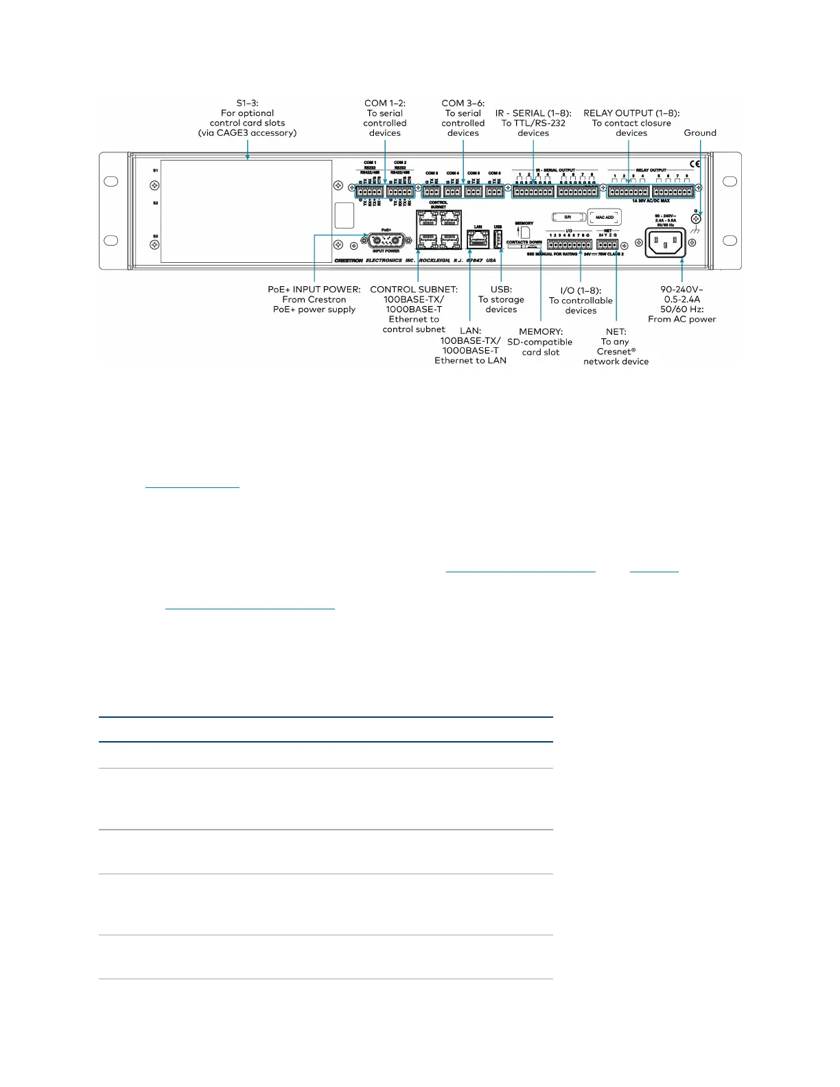
The CONTROL SUBNET ports are PoE+ PSE ports. Enabling PoE+ power sourcing requires
connection of the PoE+ INPUT POWER port to an external Crestron power supply
(PW-5430DUS, sold separately). Wiring that connects to a PoE+ PSE is designed for
intrabuilding use only.
l
If PoE+will be used, the PoE+ power supply must be connected to the control system
before it is powered on.
l
The S1, S2, and S3 slots are designed to house Crestron control cards. The CAGE3 control
cage expansion cage must be installed into the AV4 prior to using control cards. Refer to
the CAGE3 Installation Guide for more information.
l
Connect the chassis ground lug to a known earth ground circuit (such as building steel) to
ensure that the control system is grounded properly.
l
Apply power after all connections have been made.
COM1–2 Connections
Port RS-232 RS-422
1
RS-485
G GND GND GND
2
TX TX(from control
system)
TX- (from
control
system)
TX-/RX-
RX RX(to control system) RX+(to control
system)
Not used
RTS RTS(from control
system)
TX+(from
control
system)
TX+/RX+
CTS CTS(to control system) RX- (to control
system)
Not used