Product Manual — Doc. 8559B 4-Series™ Control Systems • 81
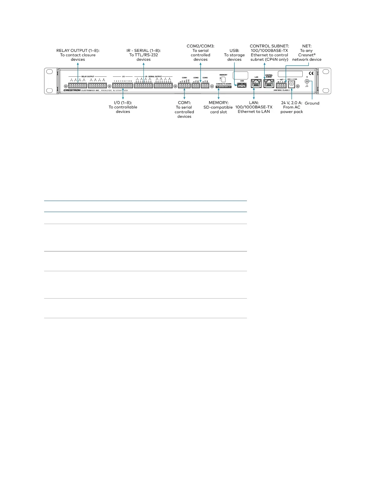
Observe the following when connecting the control system:
l
Use Crestron power supplies for Crestron equipment.
l
The control system may be powered with the included 24VDC power supply or via Cresnet®
network power with the NET port.
l
Connect the chassis ground lug to a known earth ground circuit (such as building steel) to
ensure that the control system is grounded properly.
l
Apply power after all connections have been made.
Port RS-232 RS-422
1
RS-485
G GND GND GND
2
TX TX(from control
system)
TX- (from
control
system)
TX-/RX-
RX RX(to control system) RX+(to control
system)
Not used
RTS RTS(from control
system)
TX+(from
control
system)
TX+/RX+
CTS CTS(to control system) RX- (to control
system)
Not used
1. RS-422 transmit and receive are balanced signals that require two lines plus a ground in each direction. RXD+ and
TXD+ should idle high (going low at start of data transmission). RXD- and TXD- should idle low (going high at
start of data transmission). If necessary, RXD+/RXD- and TXD+/TXD- may be swapped to maintain correct
signal levels.
2. A ground terminal connection is recommended but not required.