The one exception is when the Control Temperature Source
is set to None. In this case, the effective Reheat Setpoint is
always set equal the current Discharge Air Cooling Setpoint
Modulating HGRH Control
In the Cooling and Fan Only states, a PI Loop is used
to control the HGRH valve to maintain the discharge air
temperature at the Dehumidication Reheat Setpoint. The PI
Loop is enabled when the unit is in the Cooling or Fan Only
operating state and dehumidication becomes active.
NOTE: When congured for modulating hot gas reheat the
reheat valve is stroked open and then closed every
day at 2:00 AM as long as dehumidication is inactive
and the unit is not in the Cooling operating state at
the time.
Energy Recovery
(See page 57 for more information)
Energy recovery is provided by drawing outside air across half
of an enthalpy wheel and drawing exhaust air across the other
half. Latent and sensible heat is transferred from the hotter,
moister exhaust air to the colder dryer outside air in winter.
Latent and sensible heat is transferred from the hotter more
moist outside air to the cooler dryer exhaust air in summer.
Control consists of starting and stopping an exhaust fan,
modulating the speed of the exhaust fan, starting and stopping
the enthalpy wheel, and optionally controlling the speed of
the enthalpy wheel. The outdoor dampers are controlled in
the normal manner. The current statuses as well as editable
parameters associated with energy recovery are located in the
Energy Rec Setup menu.
Enthalpy Wheel
Normally the enthalpy wheel is turned on whenever the
exhaust fan is running and the outdoor air dampers are at the
minimum position (i.e. the unit is not in the Econo operating
state). The wheel is shut off if the exhaust fan ever turns off or
if the unit enters the Econo operating state and the dampers
are driven more than 3% above the effective minimum outdoor
air position setpoint.
There are however a number of functions that can overridden
normal wheel operation. These include Enthalpy Wheel Frost
Prevention, Enthalpy Wheel Defrost Control and Enthalpy
Wheel Capacity Limiting Control. These override functions are
described in the following sections.
Enthalpy Wheel Frost Prevention
A unit equipped with a return or space humidity sensor includes
a wheel frost prevention function that can be enabled by
setting the Fst Mgmt Meth= parameter to ExhAir. When there
is a threat of frost or condensation on the enthalpy wheel, the
wheel may be slowed down or stopped so that less enthalpy
transfer occurs and frosting or condensation on the enthalpy
wheel is avoided. In this case the frost control is based on an
Intersection Point described as follows:
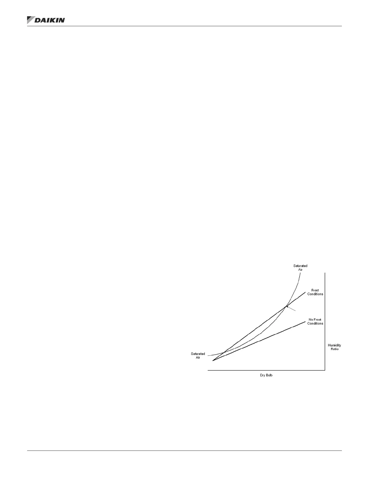
Condensation and frosting can occur on the enthalpy wheel
when the exhaust air leaving the wheel is saturated. This
condition will occur when two lines intersect on a psychometric
chart, and it will not occur when these two lines do not
intersect. One of these lines is the Humidity Ratio versus the
dry bulb for saturated air. The other line is the Humidity Ratio
versus the dry bulb temperature of the exhaust air leaving
the enthalpy wheel. The two ends of this second straight line
on a psychometric chart are the OAT at 95% RH and the
return air temperature at the return air relative humidity. One
line showing frosting conditions and another line showing no
frost conditions are shown on the sketch of a psychometric
chart shown below. A continuous calculation determines if
and at what temperatures these two lines intersect. If they do
intersect they intersect at two points. The higher of the two
points is referred to as the “Intersection Point”. When they do
not intersect, the enthalpy wheel runs at full speed. When they
do intersect, the enthalpy wheel may be slowed or stopped to
maintain the dry bulb temperature of the exhaust air leaving the
enthalpy wheel high enough to eliminate the Intersection Point
and therefore the threat of frosting conditions.
Figure 17: Exhaust Air Psychometric Chart
operator’s guIde
www.DaikinApplied.com 101 OM 1141-3 • MICROTECH UNIT CONTROLLER