usIng the Keypad/dIsplay
The keypad/display consists of a 5-line by 22 character display,
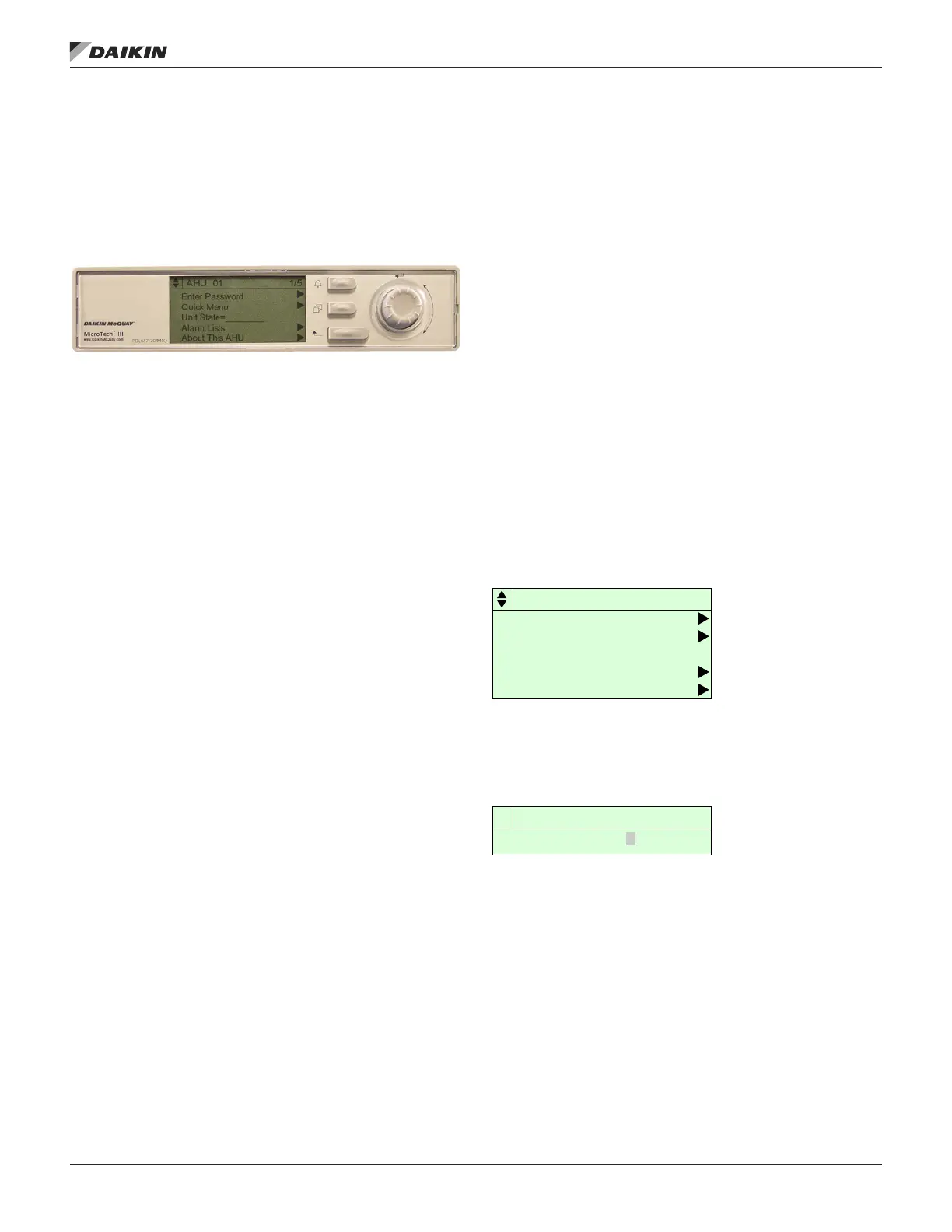
three keys and a “push and roll” navigation wheel. There is an
Alarm Button, Menu (Home) Button, and a Back Button. The
wheel is used to navigate between lines on a screen (page)
and to increase and decrease changeable values when editing.
Pushing the wheel acts as an Enter Button.
Figure 4: Keypad Controls
The rst line on each page includes the page title and the line
number to which the cursor is currently “pointing”. The line
numbers are X/Y to indicate line number X of a total of Y lines
for that page. The left most position of the title line includes an
“up” arrow to indicate there are pages “above” the currently
displayed items, a “down” arrow to indicate there are pages
“below” the currently displayed items or an “up/down” arrow
to indicate there are pages “above and below” the currently
displayed page.
Each line on a page can contain status only information or
include changeable data elds. When a line contains status
only information and the cursor is on that line all but the value
eld of that line is highlighted meaning the text is white with
a black box around it. When the line contains a changeable
value and the cursor is at that line, the entire line is highlighted.
Each line on a page may also be dened as a “jump” line,
meaning pushing the navigation wheel will cause a “jump” to
a new page. An arrow is displayed to the far right of the line to
indicate it is a “jump” line and the entire line is highlighted when
the cursor is on that line.
The keypad/display Information is organized into Menu groups;
Main Menu, Quick Menu, View/Set Unit Menu, Commission
Unit Menu, Manual Control Menu, Service Menu, Unit
Conguration Menu and Alarm list Menus.
NOTE: Only menus and items that are applicable to the
specic unit conguration are displayed.
The Main Menu allows the user to enter a password, access
the Quick Menu pages, view the current unit state, access the
Alarm List Menu as well as access to information about this
unit. The Quick Menu provides access to status information
indicating the current operating condition of the unit. The
View/Set Unit Menus include basic menus and items required
to setup the unit for general operation. These include such
things are control mode, occupancy mode and heating and
cooling setpoints. The Commission Unit Menus include more
advanced items for “tuning” unit operation such as PI loop
parameters and time delays. The Manual Control Menu allows
service personnel to test unit specic operation manually.
The Unit Conguration Menu allows the user to access to the
unit specic conguration information. These generally do not
needing changing or accessing unless there is a fundamental
change to or a problem with the unit operation. The Alarm Lists
Menu includes active alarm and alarm log information.
Passwords
Various menu functions are accessible or inaccessible,
depending on the access level of the user, and the password
they enter, if any. There are four access levels, including no
password, Level 2, Level 4, and Level 6, with Level 2 having
the highest level of access. Without entering a password, the
user has access only to basic status menu items. Entering
the Level 6 password (5321) allows access to the Alarm Lists
Menu, Quick Menu, and the View/Set Unit Menus group.
Entering the Level 4 password (2526) allows similar access
as Level 6 with the addition of the Commission Unit Menu,
Manual Control, and Service Menu groups. Entering the Level
2 password (6363) allows similar access as Level 4 with the
addition of the Unit Conguration Menu.
NOTE: Alarms can be acknowledged without entering a
password.
The main password page is displayed when the keypad/display
is rst accessed, the Home Key is pressed, the Back Key is
pressed multiple times, or if the keypad/display has been idle
longer than the Password Timeout (default 10 minutes). The
main password page provides access to enter a password,
access the Quick Menu, view the current Unit State, access the
alarm lists or view information about the unit.
Figure 5: Password Main Page
The password eld initially has a value **** where each *
represents an adjustable eld. These values can be changed
by entering the Edit Mode described below.
Figure 6: Password Entry Page
Entering an invalid password has the same effect as continuing
without entering a password. Once a valid password has been
entered, the controller allows further changes and access
without requiring the user to enter a password until either the
password timer expires or a different password is entered.
The default value for this password timer is 10 minutes. It is
changeable from 3 to 30 minutes via the Timer Settings menu.
AHU 01 1/5
Enter Password
Quick Menu
Unit State=________
Alarm Lists
Enter Password 1/1
Enter Password
usIng the Keypad/dIsplay
www.DaikinApplied.com 7 OM 1141-3 • MICROTECH UNIT CONTROLLER