IntroductIon
Getting Started
This manual contains information designed to assist the eld
technician with unit setup. The technician will need to be
familiar with the following topics at a minimum to successfully
set up unit operation.
• Keypad Navigation/Editing/Passwords
• Control Mode
• Occ Mode
• DSP (Duct Static Pressure) Setpoint
• BSP (Building Static Pressure) Setpoint
• Heat/Cool Changeover (Occupied Setpoints)
• DAT (Discharge Air Temperature) Clg Setpoint
• DAT (Discharge Air Temperature) Htg Setpoint
• Clg Enable (OAT [Outdoor Air Temperature] lockout)
• Htg Enable (OAT [Outdoor Air Temperature] lockout)
• Econo Enable (Changeover temp/Enthalpy Switch)
• Ventilation Limit/OA Damper
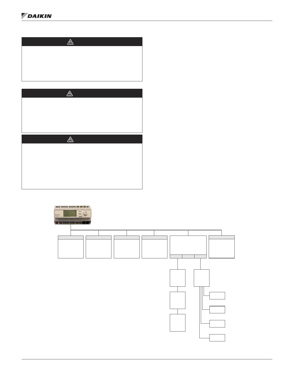
Figure 2: Inter Component Communications Diagram
WARNING
Excessive moisture in the control panel can cause
hazardous working conditions and improper equipment
operation.
When servicing this equipment during rainy weather, the
electrical components in the main control panel must be
protected from the rain.
CAUTION
Extreme temperature hazard. Can cause damage to
system components.
The MicroTech III controller is designed to operate in ambient
temperatures from -20°F to 125°F. It can be stored in ambient
temperatures from -40°F to 140°F. It is designed to be stored
and operated in relative humidity up to 95% (non-condensing).
CAUTION
Static sensitive components. A static discharge while
handling electronic circuit boards can cause damage to
the components.
Discharge any static electrical charge by touching the bare
metal inside the main control panel before performing any
service work. Never unplug any cables, circuit board terminal
blocks, relay modules, or power plugs while power is applied
to the panel.
01
SAF
ECM
INV
CMP
INV
OA
Fan1
INV
OA
Fan2
EVB
EVO
ORT
EVI
IRT
02
ExFan
ECM
10
D3
Modbus
Gateway
03
ER
VFD
(Future)
05
OA Flow
Station
(Future)
IFB
ACS1
ACS2
ACS3
07 08 09
Heat Pump Only
Heat Pump Only
ACS Comm ACS Comm
Heat Pump Only
MicroTech
®
III Unit Controller
Modbus Communication
NOTE: See “IFBCommStatus” on page 123 and “ACS1
DataRcvd” on page 124 and the “Inverter
Compressor Set-Up” on page 42 Section of
this manual if there are any questions about the
communications from component to component.
IntroductIon
www.DaikinApplied.com 5 OM 1141-3 • MICROTECH UNIT CONTROLLER