unIt confIguratIon setup
Unit Conguration Setup Menu
After the main control board application software is loaded
into the MCB, it must be “congured” for the specic
control application. This consists of setting the value of 25
conguration variables within the MCB. These variables dene
things such as the type of cooling, number of compressors and
cooling stages and the type of heat. If all of these items are not
set appropriately for the specic unit, the unit will not function
properly. The correct settings for these parameters are dened
for a given unit by the unit “Software Conguration Code.”
The “Software Conguration Code” consists of a 29-character
string of numbers and letters. The code can be found on the
Unit Software Identication Label located on the back side of
the control panel door.
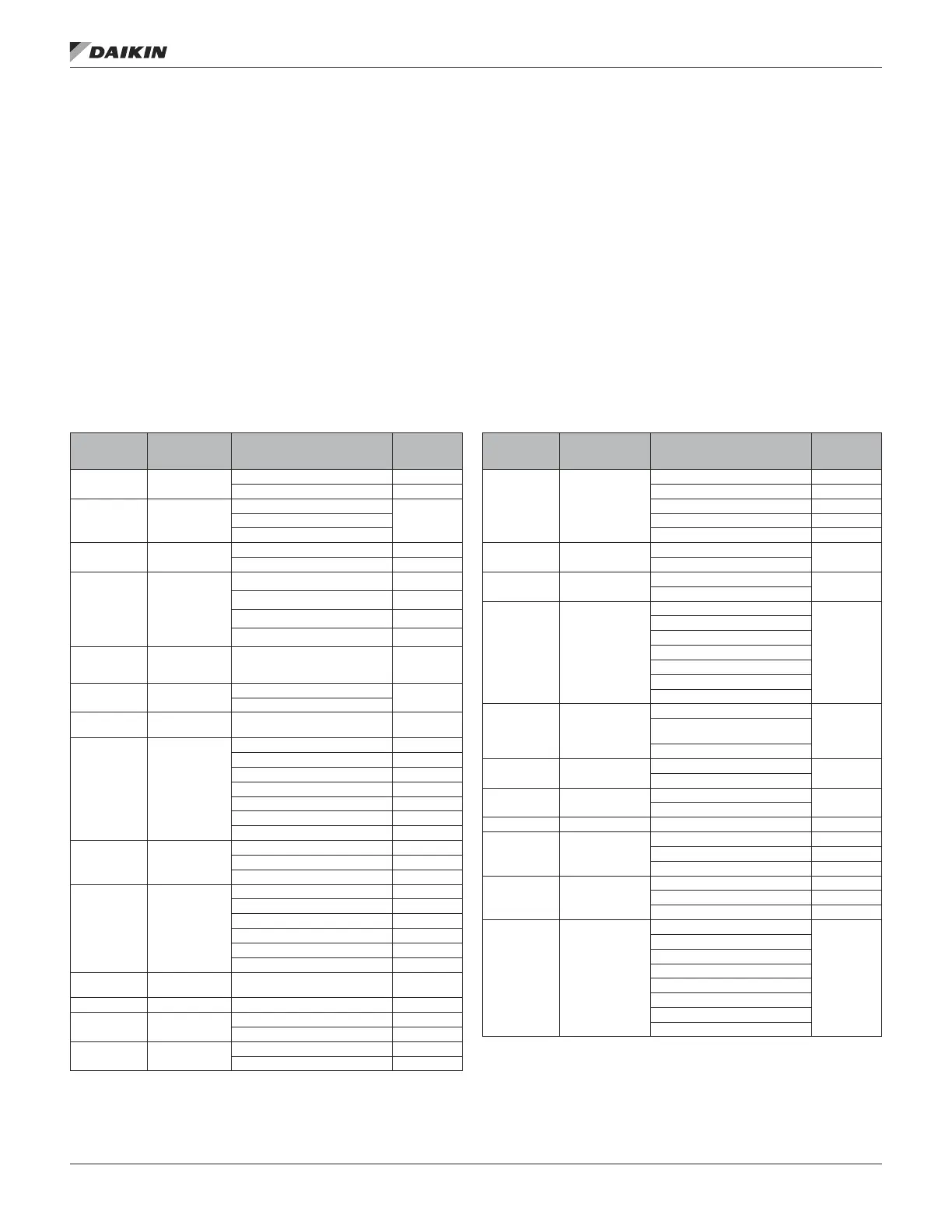
Table 53 lists the conguration code variables including the
position within the code, description of the parameter, and the
applicable settings for each. The default values are shown
in bold font. The unit is congured at the factory however
may also be congured in the eld by accessing the Unit
Conguration Menu. Once changes have been made to the
Unit Conguration Menu, the Apply Changes ag must be
changed from no to yes in order for the controller to recognize
the changes. Setting the Apply Changes ag to yes will
automatically rest the controller.
Table 53: Unit Conguration Menu
Conguration
Code
Position
Description Values (Default in Bold)
DPS
Applicability
1 Unit Type
3=Rebel Cool Only (DPS) ●
4=Rebel Heat Pump (DPH) ●
2 Control Type
0=Zone Control
●1=DAT Control
2=1ZoneVAV
3 Cooling Type
0= None NA
4=Inverter Compressorized Clg ●
4
Compressorized
Cooling
Conguration
0=None NA
1=Generic Condenser NA
L=1INV/1Circ ●
M=1INV/1STD/1Circ ●
5
Generic
Condenser
Stages
1 – 8 Stages (Default = 8) NA
6 Low Ambient
0= No
NA
1= Yes
7
Condenser
Control
8=INV ●
8 Damper Type
0=None ●
1=Single Position 30% ●
2=Single Position 100% ●
3=Economizer Airside ●
5=100%OA_DOAS ●
6=AirEcon_DOAS ●
7=30%_DOAS ●
9 OA Flow Station
0=None ●
5=Generic Flow Station ●
6=Generic Flow Station w/CO2 ●
10 Heating Type
0=None ●
1=F&BP Control NA
2=Staged ●
5=Steam or Hot Water ●
6=SCR Electric ●
7=MPSLoGas ●
11
Max Heating
Stages
1-4 Stages (Default = 1) ●
12, 13, 14 Max Heat Rise Three Digits (Default = 100) ●
15
Supply Fan
Type
6=EBMVAV ●
7=EBMCAV ●
16
Return Fan
Type
F=EBMVAV ●
G=EBMCAV ●
Conguration
Code
Position
Description Values (Default in Bold)
DPS
Applicability
17
Return/Exhaust
Fan Capacity
Control Method
0=None ●
1=Tracking NA
2=Building Pressure ●
3=Speed/Network ●
4=OADamper ●
18
Second Duct
Pressure Sensor
0=No
NA
1= Yes
19
Entering Fan
Temp Sensor
0=No
●
1=Yes
20 Energy Recovery
0=None
●
1=ConstSpdWhl/NoRH
2=VarSpdWhl/Danfoss
3=VarSpdWhl/MD2
4=VarSpdWhl/MD3
5=VarSpdWhl/ABB
6=ConstSpdWhl/wRH
21
Cooling Circuit
Type
0=Individual
NA
1=2,3 or 4 Circ. Water
Condenser
2=2 Circ. Air Condenser
22
Head Pressure
Control
0=No
NA
1=Yes
23
Bypass Valve
Control
0=Slave
NA
1=Bypass
24, 25, 26 Unit Size Three digits (Default 050) ●
27 Refrigerant Type
0=R22 NA
1=R407C NA
2=R410A ●
28 Reheat Type
0=None ●
2=ModHG ●
3=StdHtRht ●
29 Unit Voltage
0=208/60Hz
●
1=230/60Hz
2=460/60Hz
3=575/60Hz
4=208/50Hz
5=230/50Hz
6=460/50Hz
7=575/50Hz
unIt confIguratIon setup
www.DaikinApplied.com 69 OM 1141-3 • MICROTECH UNIT CONTROLLER