IntroductIon
This manual provides information regarding the MicroTech
®
III control system. It specically describes the operation and
programmable options for units with constant air volume (CAV)
control and variable air volume (VAV) control.
The MicroTech III Controller is a self contained device that is
capable of complete, stand-alone operation. Information in the
controller can be displayed and modied by using the keypad/
display in the units main control panel.
Adjusting PI Control Parameters
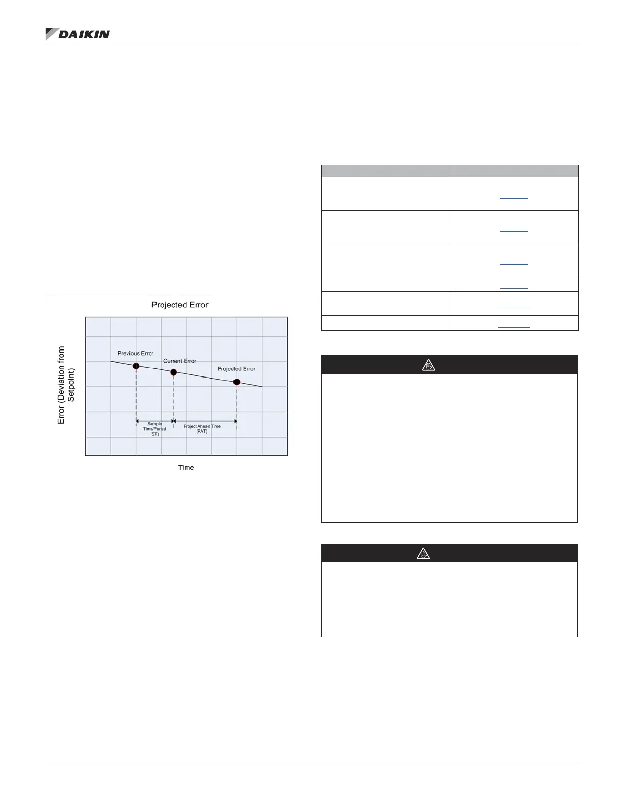
The rooftop MicroTech III controller uses a “velocity” form of
the traditional PI loop arranged such that the output is adjusted
based on a “gain” parameter multiplied by the “projected” error.
The projected error is determined based on the rate the error is
changing as shown in the gure below.
Figure 1: Projected Error Timeline
The change in output (Do) after each sample period (ST) is
given by the following equation:
Do= Gain X Projected Error.
Although it is generally recommended that they are left at the
factory settings there are four PI loop adjustment parameters
available via the MicroTech III HMI. These are Gain, Period
(ST), Project Ahead Time (PAT) and Max Change.
Generally speaking, the PAT should be set roughly equal to the
“time constant” of the system being controlled and the Period
(ST) one quarter to half the PAT. The Gain is then set to
achieve control stability. If the system is unstable (hunting) the
control is too fast and the Gain should be decreased to slow
the control response. If the system takes excessively long to
reach setpoint during transient conditions (sluggish) the Gain
can be increased to speed the control response. The goal is
an acceptable balance between these two conditions. When in
doubt these parameters should be set to the factory settings.
Additional Instructions and Information
For installation and startup instructions and general information
regarding a Rebel
™
rooftop unit, refer to the applicable model-
specic installation and maintenance manual (Table 1).
Table 1: Installation and Maintenance Resources
Unit Manual
MicroTech III Rooftop Unit
Controller - BACnet IP
Communications
IM 916
MicroTech III Rooftop Unit
Controller - BACnet MSTP
Communications
IM 917
MicroTech III Rooftop Unit
Controller - BACnet LON
Communications
IM 918
MicroTech III Unit Controller IM 919
MicroTech III Remote Unit
Interface
IM 1005
DPS 03 – 12 IM 1125
NOTICE
This equipment generates, uses, and can radiate radio
frequency energy and, if not installed and used in accordance
with this instruction manual, may cause interference to radio
communications. It has been tested and found to comply with
the limits for a Class A digital device, pursuant to part 15 of the
FCC rules. These limits are designed to provide reasonable
protection against harmful interference when the equipment
is operated in a commercial environment. Operation of this
equipment in a residential area is likely to cause harmful
interference in which case the user is required to correct
the interference at his own expense. McQuay International
disclaims any liability resulting from any interference or
for the correction thereof.
WARNING
Electric shock hazard. Can cause personal injury or
equipment damage.
This equipment must be properly grounded. Connections and
service to the MicroTech II control panel must be performed
only by personnel that are knowledgeable in the operation of
the equipment being controlled.
OM 1141-3 • MICROTECH UNIT CONTROLLER 4 www.DaikinApplied.com
IntroductIon