Outside Air Damper Control
(See page 46 for more information)
Minimum Outside Air Damper Control
Control of the dampers in the Economizer state is described
in the Economizer Control section. The outdoor air dampers
are driven open in the cooling operating state if economizer
operation is enabled and to the Minimum OA Position if
economizer operation is disabled. For all other operating
conditions, the outdoor air dampers are set to the Minimum
OA Position. The Minimum OA Position is set to zero or
closed position when the supply fan is off, the unit is in the
Recirculation state, Occupancy is set to Unocc, or the fan has
been on for less than the Zero OA Time.
As a result, the OA dampers are driven closed in night
setback, night setup, morning warm-up, and morning cool
down situations unless economizer operation is required. In all
other conditions the Minimum OA Position is equal to or below
a Ventilation Limit and equal to or above a Demand Control
Ventilation limit. For CAV units, the Ventilation Limit equals the
keypad editable Vent Limit and the Demand Control Ventilation
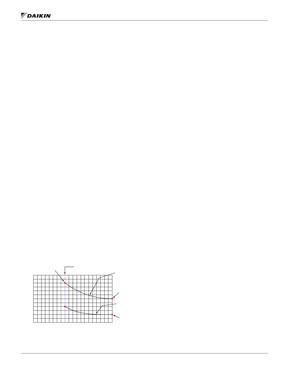
Limit equals the keypad editable DCV Limit. For VAV units, the
Ventilation Limit varies with fan speed between the editable
Vent Limit at 100% Supply Fan speed and the editable LoFlo
Vent Limit at the Min Clg Spd, as shown in Figure 18. For
VAV units, the Demand Control Ventilation Limit varies as
the Ventilation Limit value changes so that the ratio between
them remains constant. In the example shown in Figure 18
the Demand Control Ventilation Limit would always be 1/2 the
Ventilation Limit since the DCV Limit= parameter (10%) is half
of the Vent Limit= parameter (20%).
The editable parameters are to be determined when the airow
for the unit is balanced and are located in the Min OA Set-up
menu.
NOTE: The MinClgSpd is prevented from being set equal
to the Design Cooling Speed. The DCV Limit is
prevented from being set greater than the Vent Limit.
If the VentLimit or the LoFloVent Limit is set to 0, the
Ventilation Limit is overridden to 0.
Figure 18: Damper Position versus Fan Speed Chart
Cold Start Operation
A special “cold start” sequence will slow the opening of the
dampers when it is cold outdoors. This is to try to prevent
nuisance freezestat trips associated with dampers opening up
rapidly to minimum position before the heat has a chance to
ramp up. This “cold start” sequence is initiated if the following
conditions are all true:
• OAT is below the current LoDATLimit
• The unit is equipped with an Airside Economizer
• The current Unit State is beyond the Recirc
• The current Minimum Outdoor Damper Position set point
is greater than 0%
When the sequence is active the dampers will move more
slowly the colder it is outdoors. The minimum and maximum
ramp rates are adjustable via the keypad by navigating to the
Commission Unit/Min OA Set-up menu. The effective ramp rate
will vary from the minimum rate at OAT equal to -30°F to the
maximum at OAT equal to 100°F. Once the damper position
reaches a point 1% below the actual effective minimum
position normal operation will begin. If the unit enters the
Economizer operating state before the damper regulation
begins, the regulation will begin from the current economizer
position.
Minimum Outside Air Reset - None
If None is selected as the Min OA Reset Type, the Minimum
OA Position is set equal to the Ventilation Limit. The Demand
Control Ventilation Limit value is ignored when Min OA reset is
set to None.
Minimum Outside Air Reset - Network
Control
If Network is selected as the Min OA Reset Type and a valid
value for the minimum position is provided via a network the
Minimum OA Position is set equal to that value. The network
is only allowed to write a value that is between the Ventilation
Limit and the Demand Control Ventilation Limit current values.
If Network is selected as the Min OA Reset Type and a valid
value for the minimum position is not provided, the Min OA
position is set equal to the Ventilation Limit.
Minimum Outside Air Reset - External
Control
If ExtV is selected as the Min OA Reset Type, the Minimum OA
Position is calculated based on an external 0-10 VDC signal.
If ExtmA is selected as the Min OA Type, the Minimum OA
Position is calculated based on an external 0-20 mA signal.
This calculated Minimum OA Position varies linearly from zero
% at the editable minimum external signal to the maximum
value at the editable maximum external signal, but it is set no
lower than the Demand Control Ventilation Limit and no higher
than the Ventilation Limit.
10
20
30
40%
100%
(Minimum)
Airflow
Ventilation Limit
Vent Limit
(Default 20%)
DCV Limit
(Default 10%)
Min Clg Spd
(Default 40%)
Lo Flow Vent Limit
(Default 30%)
Demand Control
Ventilation OA
Damper Positio
OM 1141-3 • MICROTECH UNIT CONTROLLER 104 www.DaikinApplied.com
operator’s guIde