Instruction SiEBE18-526
154 System Configuration
20
21
22
19
18
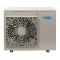
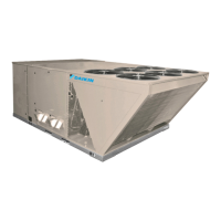
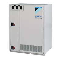
Outdoor Unit
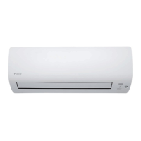
Indoor Unit
Outdoor Unit
1.
Air filter
2. Air purifying filter with photocatalytic
deodorizing function:
•
These filtersare attached to the inside of the air
filters.
3. Air inlet
4. Front grille
5. Grille tab
6. INTELLIGENT EYE sensor:
•
It detects the movements of people and
automatically switchesbetween normal operation
and energy saving operation.
7. Display
8. Air outlet
9. Flap (horizontal blade)
10. Louvers (vertical blades):
• The Louversare inside of the air outlet.
11. Operation lamp (green)
12. TIMER lamp (yellow)
13. HOME LEAVE lamp (red):
•
Lightsup when youuse HOME LEAVE
Operation.
14. Indoor Unit ON/OFF switch:
•
Push thisswitch once to start operation.
Push once again to stop it.
•
The operation mode refer to the following table.
•
Thisswitch isuseful when the remote control is
missing.
15. Packaging materials: 50 class only
•
If any packaging materialsare included, please
remove before operating.
16. Room temperature sensor:
•
It senses the air temperature around the unit.
17. Signal receiver:
•
It receivessignals from the remote control.
•
When the unit receivesasignal, you will hear a
short beep.
•
Operation start .............. beep-beep
•
Settings changed........... beep
•
Operation stop............... beeeeep
AUTO
AUTOAUTO
COOL
Mode
Temperature
setting
Air flow
rate
22°C
25°C
FTXS
FTKS
18. Air inlet: (Back and side)
19. Air outlet
20. Refrigerant piping and inter-unit cable
21. Drain hose
22. Earth terminal:
• It is inside of this cover.
Appearance of the outdoor unit may differ from some models.