Outdoor Unit SiEBE18-526
338 Removal Procedure
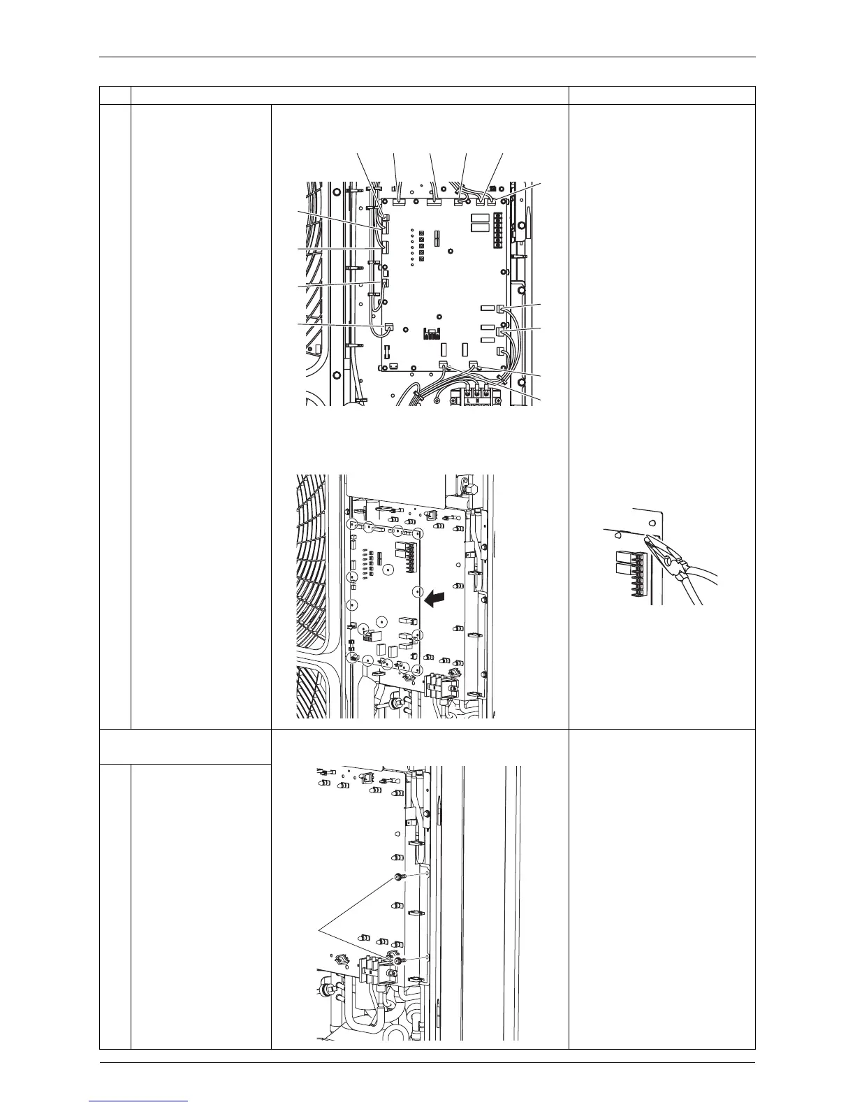
4
Disconnect the
connectors one by one.
X2A Solenoid valve (Hot gas)
X3A Solenoid valve
(Receiver gas purge)
X5A Solenoid valve
(4 way valve)
X6A Crankcase heater
X22A Transformer
X23A Transformer
X25A Connector for [X250A]
X26A Electronic expansion
valve(Main)
X28A Electronic expansion
valve(Sub cool)
X34A Discharge pipe thermistor
X37A Heat exchanger
thermistor
X44 Air thermistor
X45A Pressure sensor (Low)
X46A Pressure sensor (High)
5
Detach the sixteen
locking guard spacers.
Preferably use long nose pliers
in removing the locking guard
spacers.
6
Remove the control
PCB.
2. Removing the control
PCB mounting plate
1
Remove the two
screws.
Step
Procedure Points
X25A X34A X37A X44A X45A
X46A
X6A
X5A
X3A
X2A
X28A
X26A
X23A
X22A
(Q0464)
(Q0465)
(Q0466)
Screws
(Q0467)