Timing System Setup
11
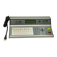
Bulkhead Deck Plate
Figure 17 illustrates a bulkhead location deck plate, which
combines the connectors from a start deck plate with the
lane data from a lane interface in the bulkhead. Typically
one of these plates is on the bulkhead and one on the
deck. Jumper cables over the deck connect the two
plates together.
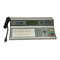
Wall Plates
A wall plate is typically where the timer is set up and
connected to the system. There are a variety of wall
plates. Two of the most common wall plates are shown in
Figure 18 and Figure 19.
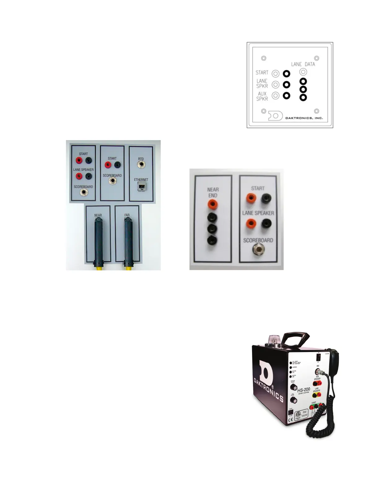
Horn Start HS-200 System
Reference Drawings:
HS-200 Horn Start: On-Deck Conguration ...................................................... DWG-185695
For typical placement of start system components, refer
to Figure 4 for on-deck installation and Figure 14 for in-
deck installation. For specic part numbers and options
available, refer to DWG-185695.
Horn Start Components
• HS-200 Horn Start unit with wired microphone (Figure 20)
or optional wireless microphone (Figure 21)
• Individual lane speaker (Figure 22); 10 max per HS-200
• Microphone extension, 15’ (4.6 m)
• Start cable, 30’ (9.1 m)
Figure 17: Bulkhead Deck Plate
Figure 18: Wall Plate (Double-Ended)
Figure 19: Wall Plate (Single-Ended)
Figure 20: HS-200 w/ Wired Mic
 Loading...