Timing System Setup
13
Equipment Connections To Use
Single ended pool with
Hy-Tek MEET MANAGER
software and a numeric
scoreboard
J2 or J3 SCOREBOARD OUTPUTS to control single or multi-line
scoreboards, event/heat, score, and lengths/record time modules
J6 RESULTS PORT or ETHERNET jack for bi-directional communication
with results programs such as Hy-Tek’s MEET MANAGER
J10 NEAR END lane harness (in-deck or on-deck)
J12 START INPUT from horn start
J13 POWER IN from wallpack transformer
CURRENT LOOP OUTPUT -
CURRENT LOOP OUTPUT +
FUNCTION
J2-J3 SCOREBOARD OUTPUTS
SHAFT
CONTACT
RING
TIP
GND
RELAY NORMALLY OPEN
RELAY NORMALLY CLOSED
CURRENT LOOP OUT +
CURRENT LOOP OUT -
J7 - SWITCH INPUTS
8
RELAY COMMON
SWITCH INPUT-GND
12
13
14
15
10
11
9
PIN # FUNCTION
SWITCH INPUT 1 +
SWITCH INPUT 2 +
4
6
7
5
2
3
1
RTD CL RX-N
RTD CL RX-P
NOT USED
J5 - RTD PORT
RTD RS-232 RX
NOT USED
NOT USED
RTD CL TX-P
RTD RS-232 TX
GND
FUNCTION
3
7
9
8
5
6
4
PIN #
1
2
NOT USED
NOT USED
NOT USED9
8
7 NOT USED
J4 - EXPANSION PORT
GND
EXPANSION RS-232 TX
EXPANSION RS-232 RX
6
5
4
3
2
1
PIN #
NOT USED
FUNCTION
NOT USED
FUNCTION
SWITCH INPUT 2 -
SWITCH INPUT 2 +
SWITCH INPUT 1 -
RELAY OUTPUT -
RELAY OUTPUT +
SWITCH INPUT 1 +
J8 - MAIN START/STOP/HORN
5
6
PIN #
1
2
3
4
SWITCH INPUT 4 +
SWITCH INPUT 4 -
SWITCH INPUT 5 +
SWITCH INPUT 3 +
SWITCH INPUT 3 -
2
3
4
5
6
SWITCH INPUT 5 -
J9 - SHOT CLOCK START/STOP
PIN #
1
FUNCTION
+VUNREG
FUNCTION
GND
J14 - NEAR LANE
NEAR CAN-H
NEAR CAN-L
4
2
3
1
PIN #
N/C
FUNCTION
14VAC
N/C
14VAC
J13 - POWER IN
PIN #
4
3
2
1
SHELL EARTH GND
START -, SWIN9-N
J12 - START INPUT
2-BLK
1-RED START +, SWIN9-P
PIN # FUNCTION
LM NEAR
CLK NEAR
J10 - NEAR END
4-RED
3-BLK
2-BLK
1-BLK GND
+VUNREG
PIN # FUNCTION
+VUNREG
CLK FAR
LM FAR
J11 - FAR END
FUNCTION
4-RED
3-BLK
2-BLK
1-BLK
PIN #
GND
PIN #
RESULTS CL RX-N
RESULTS CL RX-P
RESULTS CL TX-P
RESULTS RS-232 TX
RESULTS RS-232 RX
J6 - RESULTS PORT
GND5
NOT USED
6
8
9
7
NOT USED
FUNCTION
NOT USED
1
3
4
2
SWITCH INPUT 3 +
SWITCH INPUT 4 +
SWITCH INPUT 5 +
SWITCH INPUT 6 +
SWITCH INPUT 7 +
SWITCH INPUT 8 +
SWITCH INPUT 9 +
J15 - FAR LANE
PIN #
4
3
1
2
FAR CAN-L
FAR CAN-H
+VUNREG
FUNCTION
GND
0A-1240-0082
1001
09/28/13
AH
OMNI SPORT 2000
CONNECTOR DESIGNATIONS: OMNISPORT 2000
CBRECZI 19 JUN 02
1240 R
08 A
1=4
CBRECZI
154282
02
02 25 JAN 13 SMB
ADDED ETHERNET PORT AND AUDIO JACK. UPDATED
REAR JACKS AND LABELS.
1 04 DEC 02 CJB
CHANGED LABEL ON J6 FROM RTD PORT
TO RESULTS PORT.
AUDIO OUTPUT: 3.5mm
ETHERNET PORT:
NETWORK INTERFACE SUPPORTS
AUTO MDI/MDIX - EITHER
CABLE TYPE MAY BE USED.
DAKTRONICS, INC.
17800
Hear the console beeper via headphones
Far End (Split End) lane
harness (in-deck/on-deck)
J11 FAR END lane harness (in-deck or on-deck)
OmniSport Pro software
J4 EXPANSION PORT or ETHERNET jack for bi-directional
communication with OmniSport Pro software
Matrix scoreboard
J5 RTD PORT or ETHERNET jack for bi-directional communication with
Daktronics display control software (or CTS scoreboard, J5 only)
Track/rodeo push button
timing
J7 SWITCH INPUTS is a port for external control switches
Water polo
J8 MAIN CLK SWITCH is a game clock switch port for water polo
J9 SHOT CLK SWITCH is a shot clock switch port for water polo
Judge console
J14 NEAR END for Judge console
J15 FAR END for Judge console
A maximum of 9 judges can be plugged into either J14 or J15.
Diving has a maximum of 9 judge consoles. Synchronized swimming
has a maximum of 18 consoles. (Example: 4 judges on one side of
the dive well are plugged into J14 and 3 judges on the other side of
the pool are plugged into J15 for a total of 7 judges.)
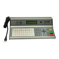
Deck Harness & Horn Start Connections
Figure 24 shows a Near End deck harness connected to J10 and the cable from the horn
start plugged into J12. Remember the GND tab on dual banana plugs lines up with the
black female connector.
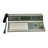
Daktronics Numeric Display Connection
Connect the 1/4” scoreboard signal cable into J2 or J3 SCOREBOARD OUTPUTS as shown
in Figure 25. Ensure the plug is fully inserted into the jack on the console.
Figure 24: Lane Data & Horn Start Plugs
Figure 25: Numeric Scoreboard Plug
 Loading...