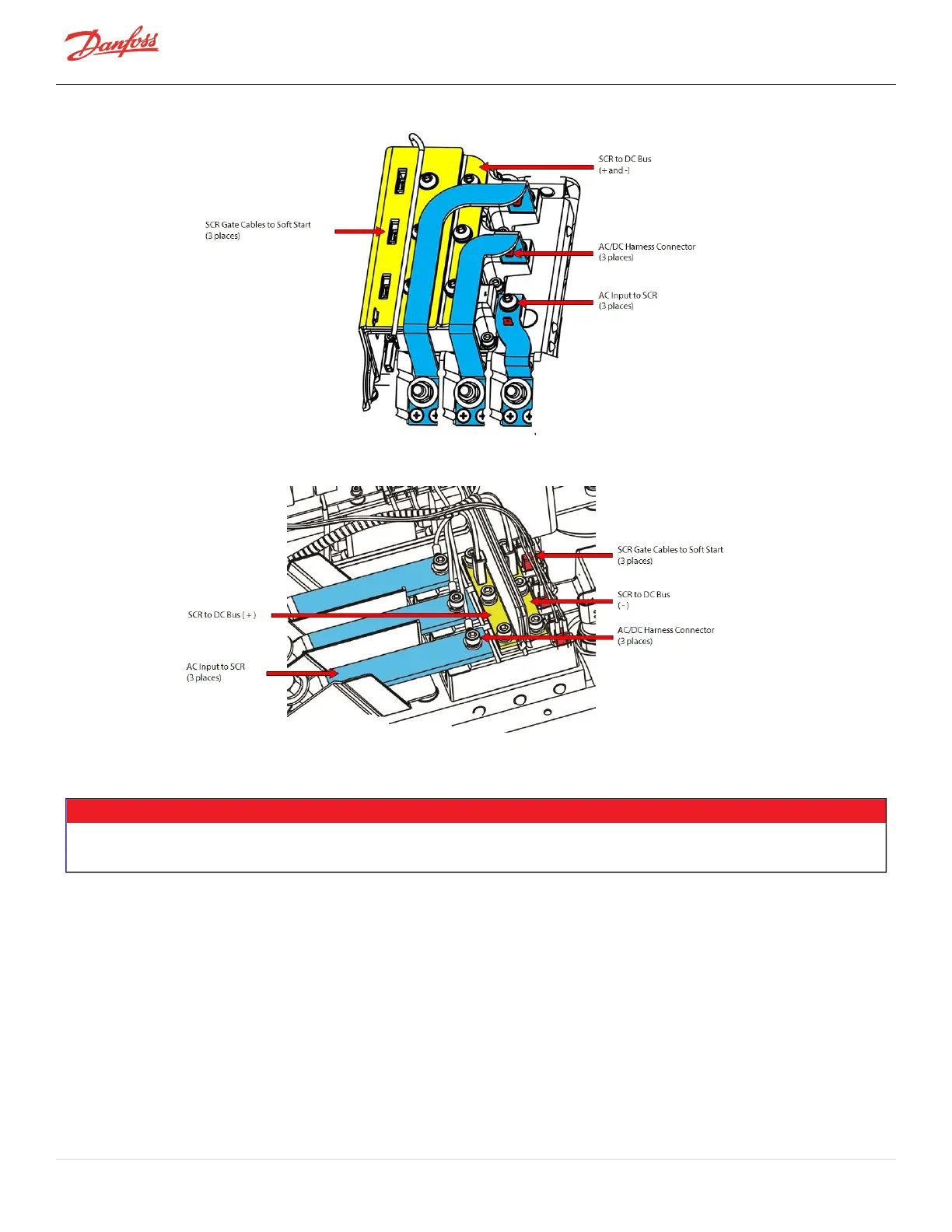
Figure 4-141 SCR Connections - TTS/TGS/TTH/TGH Rev. F and Earlier (Except TTS300/TGS230)
Figure 4-142 SCR Connections - TTS/TGS/TTH/TGH Rev. H (Except TTS300/TGS230)
4.18.2 SCR Verification
NOTE
AfaultySCRmodulecancausetheDCbusandMainsInputcurrenttobeimbalanced.ThiscanstresstheInverterandStator.IfanSCR
moduleisfoundtobefaulty,thentheInverterandStatormustalsobeverified.
4.18.2.1 Diodes Verification - Two-Hole Mount
1. IsolatecompressorpowerasdescribedinSection1.8ElectricalIsolationonpage22.
2. RemovetheDCBusBarsfromtheSCRs.RefertoSection4.21.3DCCapacitorBusBarAssemblyRemoval
andInstallationonpage168.
3. Usingamultimetersetfordiodemeasurements,placetheblack(-)leadonterminal1oftheSCRand
placethered(+)leadonterminal3.Themeasuredvalueshouldbebetween0.3Vand0.45V.Referto
Figure4-143SCRTerminals-Two-HoleMountonpage143andFigure4-144SCRTerminals-Four-Hole
Mountonpage143forterminallocations.
4. Allotherterminalsshouldreadinfinityoropeninbothdirections(polarity).RefertoTable4-28SCR
DiodeValuesonpage144.
5. PerformthistestforeachSCR.
Page 142 of 294 - M-SV-001-EN Rev. H 1/23/2023