4.30 Bearing Sensors
4.30.1 Bearing Sensor Function
Bearingsensorsfeedbackreal-timeshaftorbitinformationtothebearingcontrolloop.RefertoFigure4-252
BearingControlSignalFlowonpage226.
4.30.2 Bearing Sensor Connection
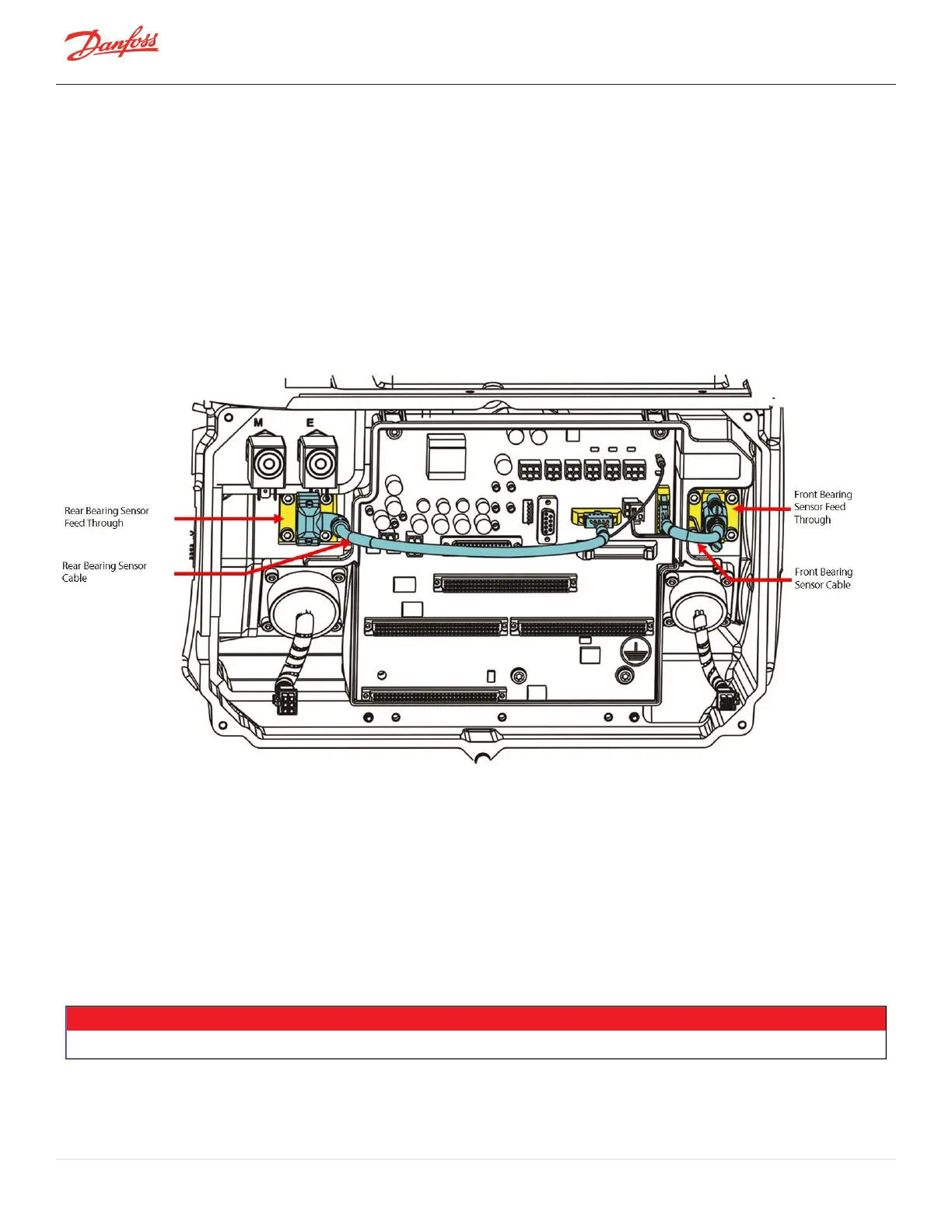
TheBearingSensorsareconnectedinternallytotheBearingSensorfeedthroughslocatedabovethefrontandrear
bearingpowerfeedthroughs.Thebearingsensorfeedthroughsareconnectedtothebearingsensorcableswhich
connecttoJ9andJ10ontheBackplane.RefertoFigure4-262BearingSensorFeedthroughs.
Figure 4-262 Bearing Sensor Feedthroughs
4.30.3 Bearing Sensor Verification
4.30.3.1 Bearing Sensor Resistance Verification
1. Isolatecompressorpower.
2. RemovetheServiceSideCover.RefertoSection4.1.3.1ServiceSideCoverRemovalandInstallationon
page54.
3. WaitfortheLEDsontheBackplanetoturnoff.
4. PlacemeterleadsonbearingsensorfeedthroughpinsoutlinedinTable4-48BearingSensorCoil
Resistanceonpage237.RefertoFigure4-263BearingSensorPinLocationsonpage237forpin
locations.
NOTE
TherearenoconnectionsonPins1&4and1&9ontheRearBearingSensorFeedthrough.
Page 236 of 294 - M-SV-001-EN Rev. H 1/23/2023